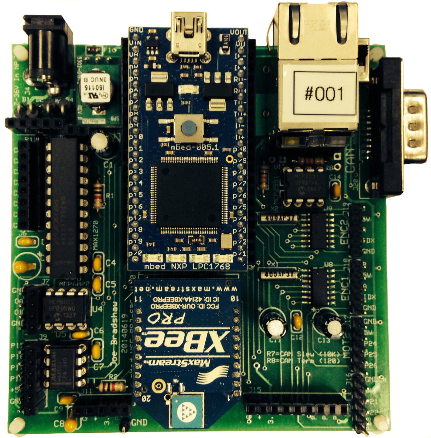
C Library for mbedWSE project based single board computer for hardware peripherals
Dependents: Lab7_wse Lab7_wse_student mbed_WSEPRJSBC_EncoderTest mbed_WSEPRJSBC_ADC_test ... more
Weapons and Systems Engineering mbed based single board computer

Contains C library function listing for hardware peripheral support. Includes functions for +/-10V 12-bit 8-Channel analog-to-digital converter (ADC), 10-bit 2-Channel digital-to-analog converter (DAC), motor control/servo ports, and quadrature encoder ports. Board includes physical Ethernet, USB Host, and CAN bus interfaces. Also includes xbee socket and external I/O pins straight to processor for on-board I2C, SPI, ADC, and DAC.
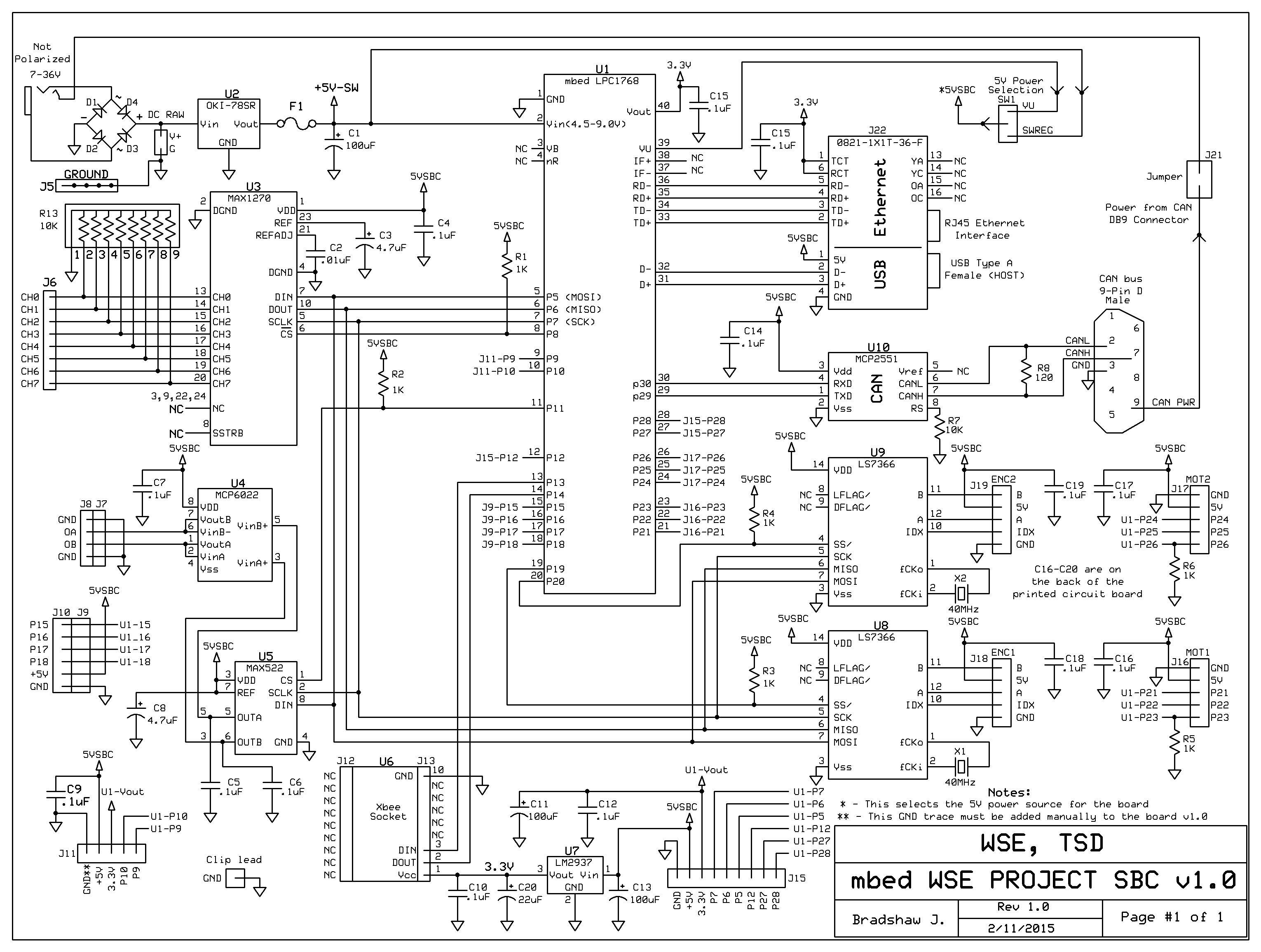
Schematic

Description
This single board computer was designed for the Weapons and Systems Engineering department at the US Naval Academy. The board encompasses a multitude of functional capability for interfacing to a variety of sensors and actuators used in embedded control systems. The board can be powered from a 7-36V DC / AC power supply using a 2.1mm standard barrel connector. The on board bridge rectifier composed of individual diodes allows either polarity on the connector power supply. The four primary external integrated circuits on the board all use the SPI bus for communication. The four primary components are the analog to digital converter, the digital to analog converter, and the two dedicated encoder/counter IC's. The encoder/counter IC's off-load the micro-processor from the burden of external interrupts during high frequency edge detection. The IC's offer 32-bit resolution counting/quadrature decoding, rollover and status information, and index detection for absolute position encoder interfacing. The MAX1270 analog to digital converter (ADC) was chosen for its internal reference and bi-polar voltage input range and scaling program-ability (0-5V, 0-10V, +/-5V, +/-10V). The ADC provides 12-bit resolution at these voltage ranges and are individually channel select-able. Note that careful attention must be used when driving the ADC inputs when in Bipolar operation. An Op-Amp with insufficient current drive capability (milli-amps) will be unable to overcome the internal voltage reference on the input pin due to impedance mismatch/ output current drive capability. This should be checked with an oscilloscope on the input pin if discrepancies between measured voltage values and ADC results exist.
The MAX522 DAC provides 0-5V 10-bit voltage resolution. The range is dependent on the selected 5V board voltage reference source (external 5V switching regulator vs. USB power supply). The board power supply 5V reference can be read by connecting the supply to an external ADC channel and reading the voltage on the 0-10V range.
/media/uploads/jebradshaw/mbed_wseprojsbc_schematic_20140922.pdf - Schematic in PDF
Test Program
/media/uploads/jebradshaw/main_mbedwsesbctest.cpp - Program for testing the library, control the SBC with serial commands
http://developer.mbed.org/users/jebradshaw/code/mbed_WSEPRJSBC_EncoderTest/ - Program for testing the Quadrature Encoder Channels
http://developer.mbed.org/users/jebradshaw/code/mbed_WSEPRJSBC_ADC_test/ - Program to read two channels from the MAX1270 ADC in +/- 10V operation.
http://mbed.org/handbook/Windows-serial-configuration - Link to Serial Driver Installation instructions
Datasheets
/media/uploads/jebradshaw/oki-78sr.pdf - 5V switching regulator
/media/uploads/jebradshaw/ls7366r_w_program.pdf - Encoder IC's
/media/uploads/jebradshaw/max1270.pdf - ADC 8-Channel 12-bit 5V to 10V single/bi-polar input
/media/uploads/jebradshaw/max522.pdf - DAC 2-Channel 0-5V 10-bit
/media/uploads/jebradshaw/mcp2551_can_transceiver.pdf - CAN Transceiver
/media/uploads/jebradshaw/0821-1x1t-36-f.pdf - Ethernet Jack
/media/uploads/jebradshaw/190-009-263r001.pdf - CAN connector
Printed Circuit Board (ExpressPCB)
/media/uploads/jebradshaw/mbedprjv10_20140916.pcb
Partslist (partial)
/media/uploads/jebradshaw/mbedprjv10_partslist.pdf
mbedWSEsbc.h
- Committer:
- jebradshaw
- Date:
- 2016-10-11
- Revision:
- 14:2564f54c89df
- Parent:
- 13:321d6fdc40e6
File content as of revision 14:2564f54c89df:
/* C Library for the WSE-PROJ-SBC
 J Bradshaw
 20140912
 20140918 J Bradshaw - Found CS mistake in Encoder routines
    Added comments in Init function, encoder functions
 20150210 J Bradshaw - Initialized DigitalOuts with pre-defined logic
   levels (CS's high, etc)
 20161011 J Bradshaw - Changed MAX1270 ADC SCLK to 5MHz and format(12, 0)
   for conversion mode to match datasheet (200ns SCLK max PW high and low)
*/


// LS7366 ENCODER IC DEFINITIONS
//=============================================================================
// Four commands for the Instruction Register (B7,B6) - LS7366
//=============================================================================
#define CLR     0x00    //Clear Instruction
#define RD      0x01    //Read Instruction
#define WR      0x02    //Write Instruction
#define LOAD    0x03    //Load Instruction

//=============================================================================
// Register to Select from the Instruction Register (B5,B4,B3) - LS7366
//=============================================================================
#define NONE        0x00    //No Register Selected
#define MDR0        0x01    //Mode Register 0
#define MDR1        0x02    //Mode Register 1
#define DTR         0x03    //Data Transfer Register
#define CNTR        0x04    //Software Configurable Counter Register
#define OTR         0x05    //Output Transfer Register
#define STR         0x06    //Status Register
#define NONE_REG    0x07    //No Register Selected

// Set-up hardwired IO
SPI spi_max1270(p5, p6, p7);
SPI spi(p5, p6, p7);
DigitalOut max1270_cs(p8, 1);  //CS for MAX1270 ADC (U3)
DigitalOut max522_cs(p11, 1);  //CS for MAX522 DAC (U5)

DigitalOut ls7166_cs1(p19, 1); //CS for LS7366-1 (U8)
DigitalOut ls7166_cs2(p20, 1); //CS for LS7366-2 (U9)

DigitalOut mot1_ph1(p21, 0);
DigitalOut mot1_ph2(p22, 0);
PwmOut mot_en1(p23);

DigitalOut mot2_ph1(p24, 0);
DigitalOut mot2_ph2(p25, 0);
PwmOut mot_en2(p26);

DigitalOut led1(LED1, 0);
DigitalOut led2(LED2, 0);
DigitalOut led3(LED3, 0);
DigitalOut led4(LED4, 0);

Serial pc(USBTX, USBRX); // tx, rx for serial USB interface to pc
Serial xbee(p13, p14); // tx, rx for Xbee
Timer t; // create timer instance

// ------ Prototypes -----------
int read_max1270(int chan, int range, int bipol);
float read_max1270_volts(int chan, int range, int bipol);
void mot_control(int drv_num, float dc);
void LS7366_cmd(int inst,  int reg);
long LS7366_read_counter(int chan_num);
void LS7366_quad_mode_x4(int chan_num);
void LS7366_reset_counter(int chan_num);
void LS7366_write_DTR(int chan_num,long enc_value);
void write_max522(int chan, float volts);

//---- Function Listing -------------------------------
int read_max1270(int chan, int range, int bipol){
    int cword=0x80;     //set the start bit

    spi_max1270.frequency(5000000); //5MHz Max
    spi_max1270.format(8, 0);   // 8 data bits, CPOL0, and CPHA0 (datasheet Digital Interface)

    cword |= (chan << 4);   //shift channel
    cword |= (range << 3);
    cword |= (bipol << 2);

    max1270_cs = 0;

    spi_max1270.write(cword);
    wait_us(15);    //15us
    spi_max1270.format(12, 0);

    int result = spi_max1270.write(0);

    max1270_cs = 1;
    spi_max1270.format(8, 0);
    return result;
}

float read_max1270_volts(int chan, int range, int bipol){
    float rangevolts=0.0;
    float volts=0.0;
    int adc_res;

    //read the ADC converter
    adc_res = read_max1270(chan, range, bipol) & 0xFFF;

   //Determine the voltage range
   if(range)  //RNG bit
     rangevolts=10.0;
   else
     rangevolts=5.0;

   //bi-polar input range
   if(bipol){ //BIP is set, input is +/-
     if(adc_res < 0x800){ //if result was positive
      volts = ((float)adc_res/0x7FF) * rangevolts;
     }
     else{  //result was negative
      volts = -(-((float)adc_res/0x7FF) * rangevolts) - (rangevolts * 2.0);
     }
   }
   else{  //input is positive polarity only
      volts = ((float)adc_res/0xFFF) * rangevolts;
   }

   return volts;
}

//Motor control routine for PWM on 5 pin motor driver header
// drv_num is 1 or 2 (defaults to 1, anything but 2)
// dc is signed duty cycle (+/-1.0)

void mot_control(int drv_num, float dc){
    if(dc>1.0)
        dc=1.0;
    if(dc<-1.0)
        dc=-1.0;

    if(drv_num != 2){
        if(dc > 0.0){
            mot1_ph2 = 0;
            mot1_ph1 = 1;
            mot_en1 = dc;
        }
        else if(dc < -0.0){
            mot1_ph1 = 0;
            mot1_ph2 = 1;
            mot_en1 = abs(dc);
        }
        else{
            mot1_ph1 = 0;
            mot1_ph2 = 0;
            mot_en1 = 0.0;
        }
    }
    else{
        if(dc > 0.0){
            mot2_ph2 = 0;
            mot2_ph1 = 1;
            mot_en2 = dc;
        }
        else if(dc < -0.0){
            mot2_ph1 = 0;
            mot2_ph2 = 1;
            mot_en2 = abs(dc);
        }
        else{
            mot2_ph1 = 0;
            mot2_ph2 = 0;
            mot_en2 = 0.0;
        }
    }
}

//----- LS7366 Encoder/Counter Routines --------------------
void LS7366_cmd(int inst,  int reg){
    char cmd;

    spi.format(8, 0);
    spi.frequency(2000000);
    cmd = (inst << 6) | (reg << 3);
//    printf("\r\ncmd=0X%2X", cmd);
    spi.write(cmd);
}

long LS7366_read_counter(int chan_num){
    union bytes{
        char byte_enc[4];
        long long_enc;
    }counter;

    counter.long_enc = 0;

    spi.format(8, 0);
    spi.frequency(2000000);

    if(chan_num!=2){
        ls7166_cs1 = 0;
        wait_us(1);
        LS7366_cmd(LOAD,OTR);//cmd = 0xe8, LOAD to OTR
        ls7166_cs1 = 1;
        wait_us(1);
        ls7166_cs1 = 0;
    }
    else{
        ls7166_cs2 = 0;
        wait_us(1);
        LS7366_cmd(LOAD,OTR);//cmd = 0xe8, LOAD to OTR
        ls7166_cs2 = 1;
        wait_us(1);

        ls7166_cs2 = 0;
    }
    wait_us(1);
    LS7366_cmd(RD,CNTR);  //cmd = 0x60, READ from CNTR
    counter.byte_enc[3] = spi.write(0x00);
    counter.byte_enc[2] = spi.write(0x00);
    counter.byte_enc[1] = spi.write(0x00);
    counter.byte_enc[0] = spi.write(0x00);

    if(chan_num!=2){
        ls7166_cs1 = 1;
    }
    else{
        ls7166_cs2 = 1;
    }

    return counter.long_enc;  //return count
}

void LS7366_quad_mode_x4(int chan_num){

    spi.format(8, 0);
    spi.frequency(2000000);

    if(chan_num!=2){
        ls7166_cs1 = 0;
    }
    else{
        ls7166_cs2 = 0;
    }
    wait_us(1);
    LS7366_cmd(WR,MDR0);// Write to the MDR0 register
    wait_us(1);
    spi.write(0x03); // X4 quadrature count mode
    if(chan_num!=2){
        ls7166_cs1 = 1;
    }
    else{
        ls7166_cs2 = 1;
    }
}

void LS7366_reset_counter(int chan_num){
    spi.format(8, 0);           // set up SPI for 8 data bits, mode 0
    spi.frequency(2000000);     // 2MHz SPI clock

    if(chan_num!=2){            // activate chip select
        ls7166_cs1 = 0;
    }
    else{
        ls7166_cs2 = 0;
    }
    wait_us(1);                 // short delay
    LS7366_cmd(CLR,CNTR);       // Clear the counter register
    if(chan_num!=2){            // de-activate chip select
        ls7166_cs1 = 1;
    }
    else{
        ls7166_cs2 = 1;
    }
    wait_us(1);                 // short delay

    if(chan_num!=2){            // activate chip select
        ls7166_cs1 = 0;
    }
    else{
        ls7166_cs2 = 0;
    }
    wait_us(1);                 // short delay
    LS7366_cmd(LOAD,CNTR);      // load counter reg
    if(chan_num!=2){            // de-activate chip select
        ls7166_cs1 = 1;
    }
    else{
        ls7166_cs2 = 1;
    }
}

void LS7366_write_DTR(int chan_num, long enc_value){
    union bytes                // Union to speed up byte writes
    {
        char byte_enc[4];
        long long_enc;
    }counter;

    spi.format(8, 0);           // set up SPI for 8 data bits, mode 0
    spi.frequency(2000000);     // 2MHz SPI clock

    counter.long_enc = enc_value; // pass enc_value to Union

    if(chan_num!=2){              // activate chip select
        ls7166_cs1 = 0;
    }
    else{
        ls7166_cs2 = 0;
    }
    wait_us(1);                 // short delay
    LS7366_cmd(WR,DTR);         // Write to the Data Transfer Register
    spi.write(counter.byte_enc[3]); // Write the 32-bit encoder value
    spi.write(counter.byte_enc[2]);
    spi.write(counter.byte_enc[1]);
    spi.write(counter.byte_enc[0]);
    if(chan_num!=2){            // de-activate the chip select
        ls7166_cs1 = 1;
    }
    else{
        ls7166_cs2 = 1;
    }

    wait_us(1);                 // short delay
    if(chan_num!=2){            // activate chip select
        ls7166_cs1 = 0;
    }
    else{
        ls7166_cs2 = 0;
    }
    wait_us(1);                 // short delay
    LS7366_cmd(LOAD,CNTR);      // load command to the counter register from DTR
    if(chan_num!=2){            // de-activate chip select
        ls7166_cs1 = 1;
    }
    else{
        ls7166_cs2 = 1;
    }
}

//------- MAX522 routines ---------------------------------
void write_max522(int chan, float volts){
    int cmd=0x20;   //set UB3
    int data_word = (int)((volts/5.0) * 256.0);
    if(chan != 2)
        cmd |= 0x01;    //set DAC A out
    else
        cmd |= 0x02;    //set DACB out

 //   pc.printf("cmd=0x%4X  data_word=0x%4X \r\n", cmd, data_word);

    spi.format(8, 0);
    spi.frequency(2000000);
    max522_cs = 0;
    spi.write(cmd & 0xFF);
    spi.write(data_word & 0xFF);
    max522_cs = 1;
}

void mbedWSEsbcInit(unsigned long pcbaud){
    led1 = 0;           //Initialize all LEDs as off
    led2 = 0;
    led3 = 0;
    led4 = 0;
    max1270_cs = 1;     //Initialize all chip selects as off
    max522_cs = 1;
    ls7166_cs1 = 1;
    ls7166_cs2 = 1;

    wait(.2);   //delay at beginning for voltage settle purposes

    mot_en1.period_us(50);   //20KHz for DC motor control PWM
    pc.baud(pcbaud); //Set up serial port baud rate
    pc.printf("\r\n");
    xbee.baud(9600);

    LS7366_reset_counter(1);
    LS7366_quad_mode_x4(1);
    LS7366_write_DTR(1,0);

    LS7366_reset_counter(2);
    LS7366_quad_mode_x4(2);
    LS7366_write_DTR(2,0);

    t.start();  // Set up timer
}//mbedWSEsbc_init()