Serial interface for controlling robotic arm.
This program uses a LPC1768 processor for controlling a robotic arm. The basis for the program is the Axis () class which uses a PID controller to actuate a DC motor with quadrature encoder feedback.
Youtube video of robotic arm using the 6-axis controller performing an internally programmed gate, then performing the home function.
https://developer.mbed.org/users/jebradshaw/code/Axis/
The Axis Class has 3 dependencies (MotCon, LS7366LIB, and PID). The class encapsulates the required functionality of controlling a DC motor with encoder feedback through pin assignments, an SPI bus, and a pointer for the limit switch source.
The LS7366 encoder interface IC off-loads the critical time and counting requirements from the processor using an SPI bus interface for the class. The Axis class then uses a state machine to perform trapezoidal movement profiles with a Ticker class. Parameters can be adjusted through the serial interface using a FT232RL USB to serial interface IC for computer communication.
The MotCon class is a basic class that defines a PWM output pin and a single direction signal intended to control an H-Bridge motor driver IC. I used an MC33926 motor driver for each motor which are rated at 5.0-28V and 5.0 amp peak, with an RDSon max resistance of 225 milli-ohms. This part also has 3.0V to 5V TTL/CMOS inputs logic levels and various protection circuitry on board. I also liked this particular motor driver chip because you can use a PWM frequency of up to 20KHz, getting the frequency out of the audio range.
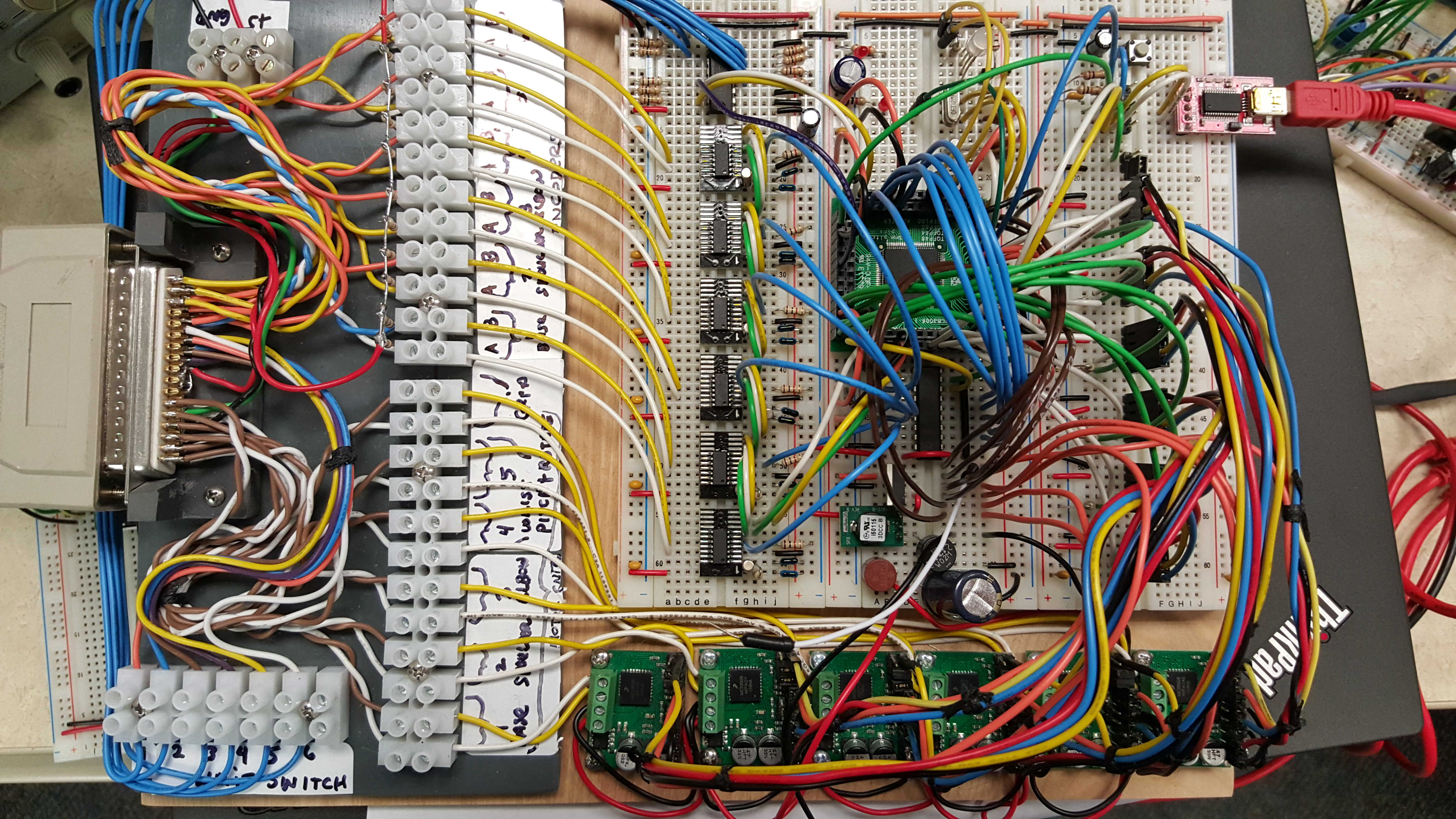
Above is the prototype for the controller. Originally, a PCF8574 I/O expander was used to read the limit switches by the I2C bus. This has now been re-written to use 6 external interrupts directly for the limit/homing switches. Six motor driver breakout boards using the MC33926 motor driver chip were used to drive the motors.
I use the mbed online compiler to generate the .bin file, use bin2hex to convert it and upload the hex file using Flash Magic to the processor with the serial bootloader. I prefer to use the FT232RL usb to serial converter IC for PC comms due to the high level of reliability and USB driver support (typically already built in Windows 7+). I've started putting this on a PCB and hope to finish by the end of the month (Dec 2015).
Well 3 months later, I've completed the first PCB prototype. A few minor errors but it's working!!
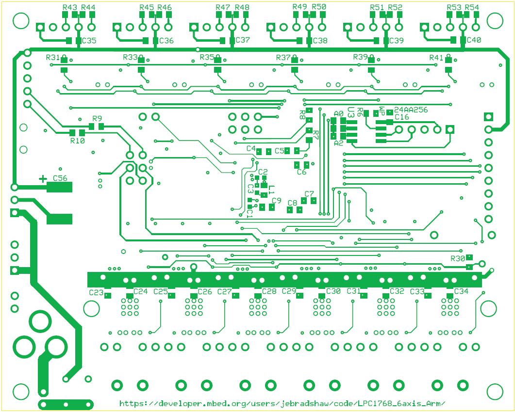
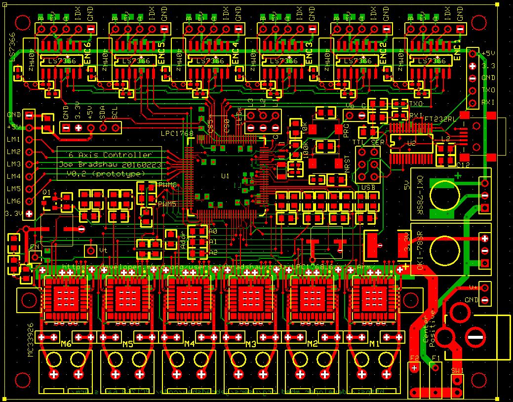 Express PCB Artwork
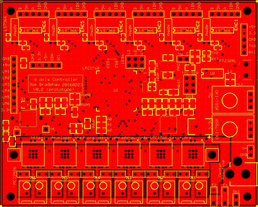 Inner Power Layer Breakup for motor current
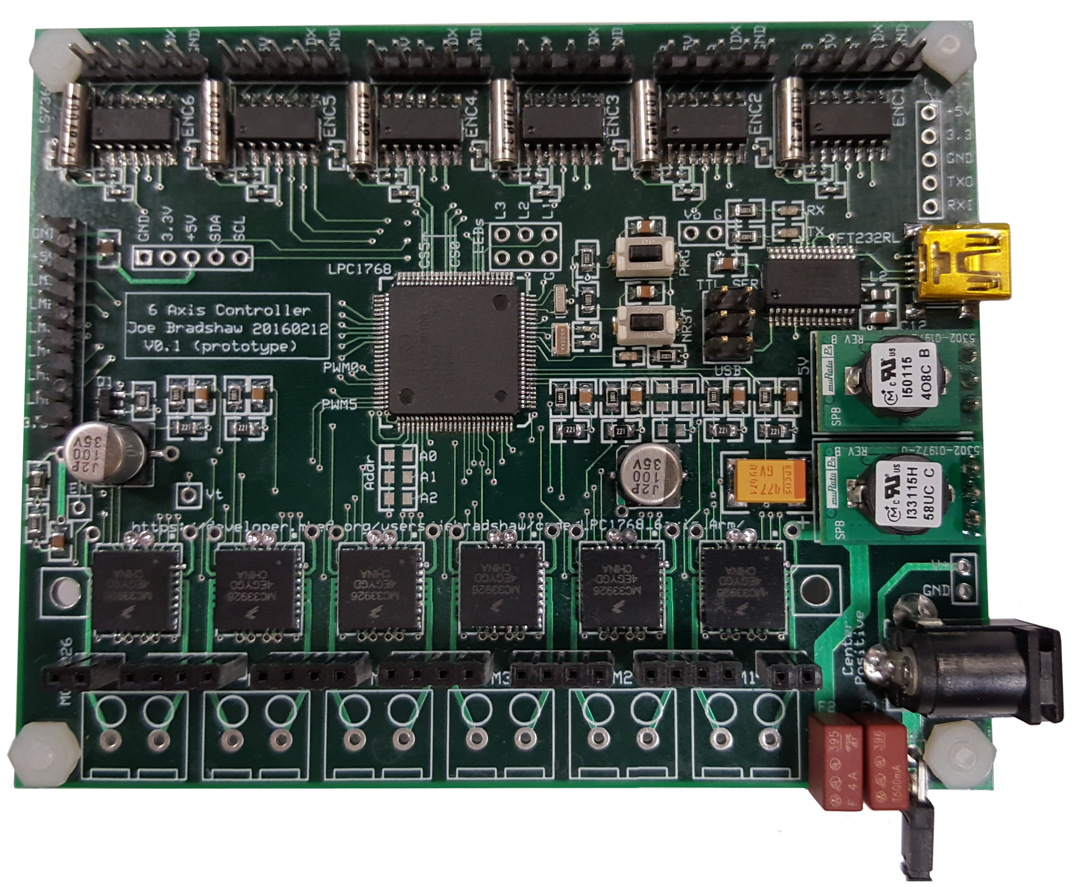 First Prototype
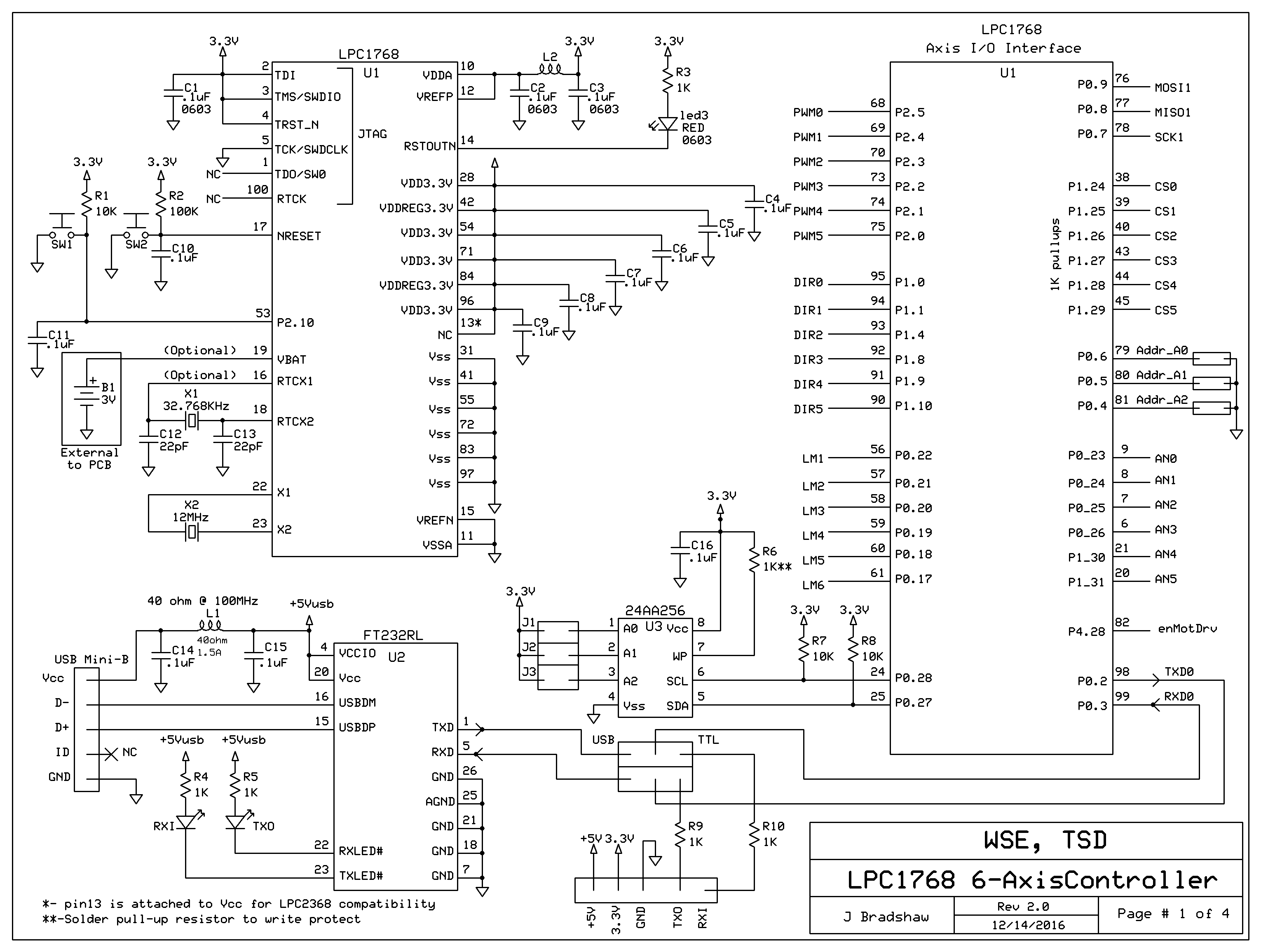
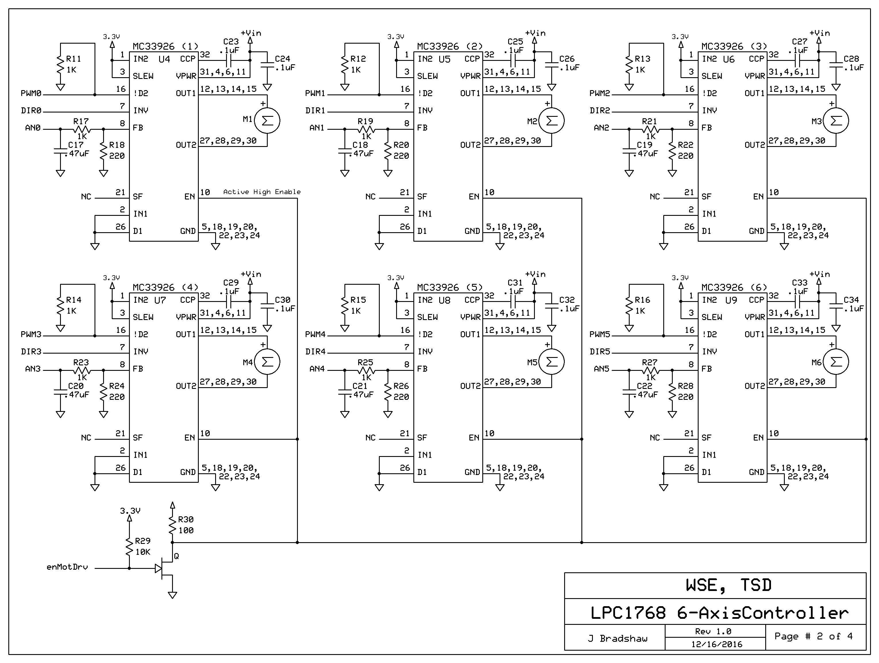
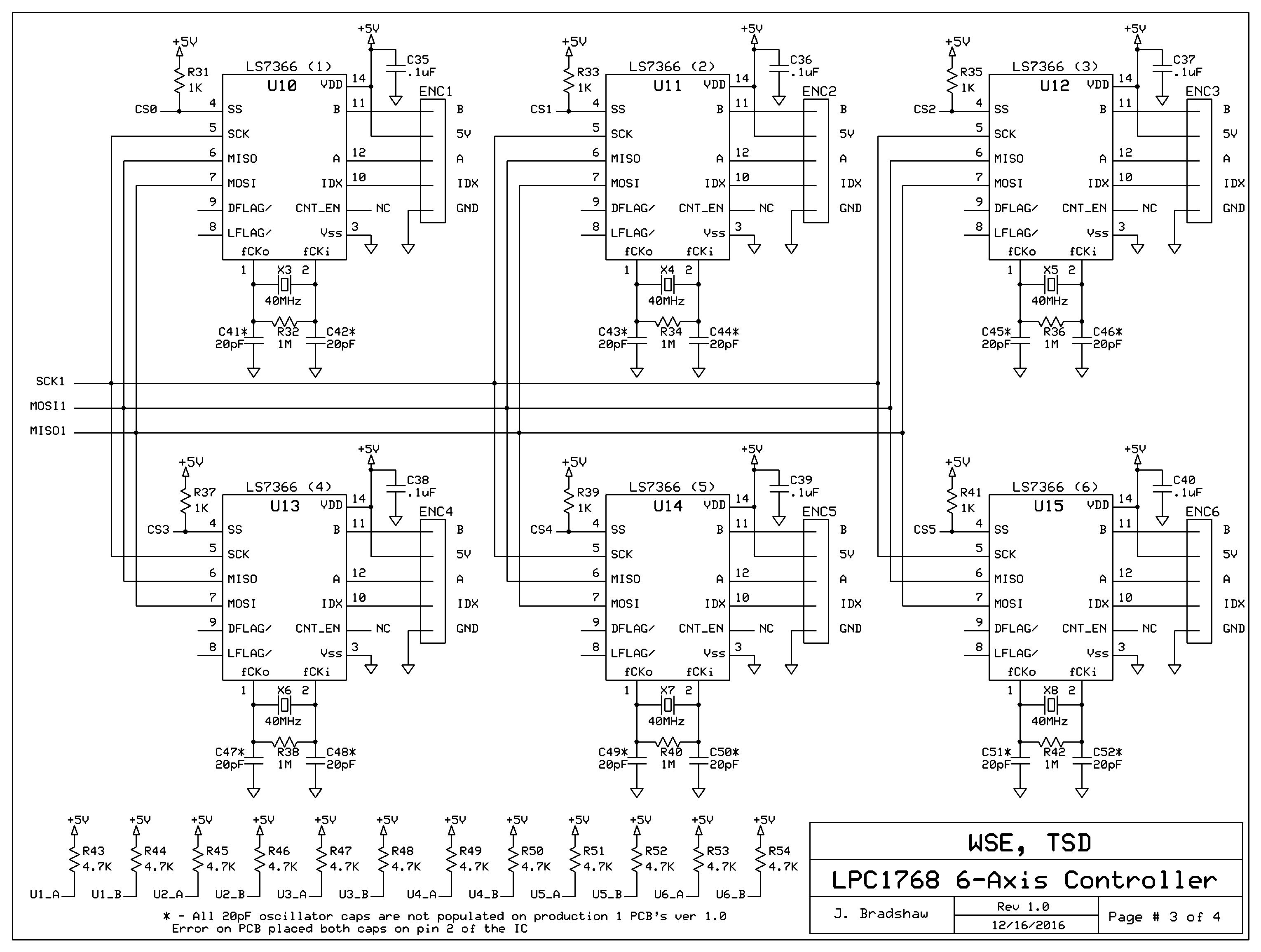
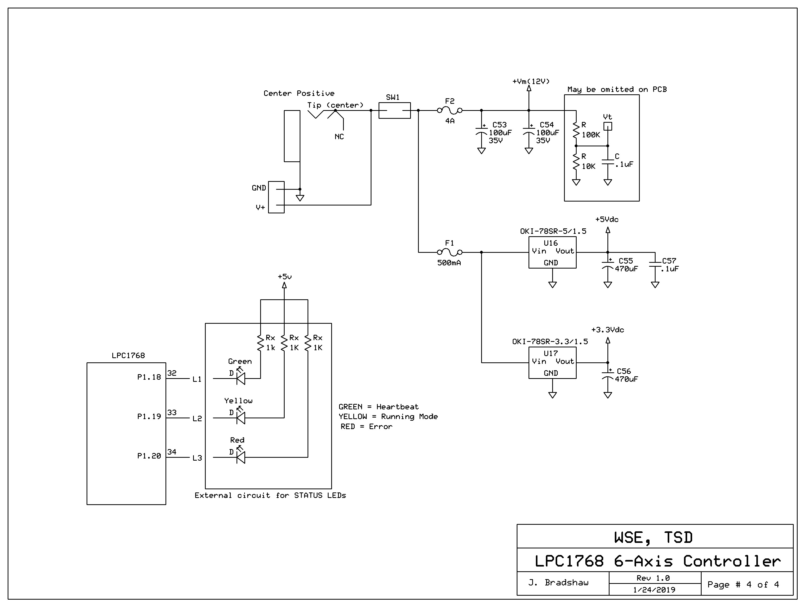
Latest documentation (schematic and parts layout) can be found here Download and open with Adobe /media/uploads/jebradshaw/axiscontroller_schematics_v2.0.pdf
Latest PCB File (Express PCB) /media/uploads/jebradshaw/lpc1768_axiscontroller_20161216.pcb
Parts Layout
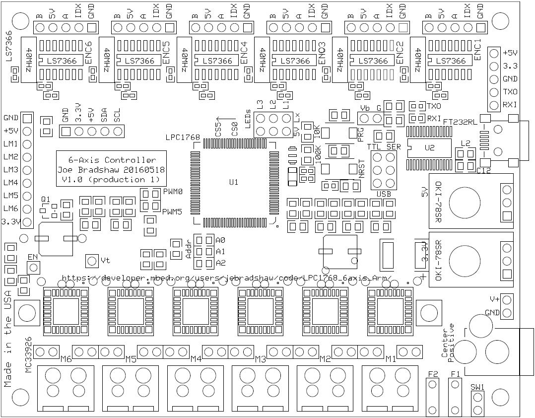
Python script for converting mbed .bin output to intel hex format (no bin2hex 64K limit) https://pypi.python.org/pypi/IntelHex
Example batch script for speeding up conversion process for FlashMagic (http://www.flashmagictool.com/) programming of board /media/uploads/jebradshaw/axisconvert.bat
https://os.mbed.com/users/jebradshaw/code/axis_ScorbotController_20180706/
Latest firmware: 20190823 - /media/uploads/jebradshaw/axis_scorbotcontroller_20190823_velocity_test.lpc1768.bin
Diff: lpc_axis.cpp
- Revision:
- 4:890c104546e9
- Parent:
- 3:1892943e3f25
--- a/lpc_axis.cpp	Thu Dec 17 19:47:39 2015 +0000
+++ b/lpc_axis.cpp	Mon Dec 28 19:59:24 2015 +0000
@@ -5,18 +5,20 @@
 // 20150731
 // 20150827 - Got Ticker Trapeziodal profile command working (moveTrapezoid, muveUpdate)
 // 20150924 - Port from the mbed to the LPC1768 processor for the 6 axis robotic arm controller
+// 20151218 - Eliminated PCF8574 I2C I/O expander and attached limit switches to P0_22 - P0_17
+//             pins as external interrupts.

 #include "mbed.h"
 #include "Axis.h"
 #include "stdlib.h"
-#include "PCF8574.h"    //library for the I/O expander (limit switches)

 #include <string>

 #define PI 3.14159
-#define PCF8574_ADDR 0    // I2c PCF8574 address is 0x00
 #define SP_TOL 100  // SET POINT TOLERANCE is +/- tolerance for set point command

+// Assign interrupt function to pin P0_17 (mbed p12)
+
 DigitalOut led1(P1_18); //blue
 DigitalOut led2(P1_20); //
 DigitalOut led3(P1_21);
@@ -24,6 +26,20 @@
 Serial pc(P0_2, P0_3);    //pc serial interface (USB)
 SPI spi(P0_9, P0_8, P0_7);        //MOSI, MISO, SCK

+DigitalIn limit1_pin(P0_22);
+DigitalIn limit2_pin(P0_21);
+DigitalIn limit3_pin(P0_20);
+DigitalIn limit4_pin(P0_19);
+DigitalIn limit5_pin(P0_18);
+DigitalIn limit6_pin(P0_17);
+
+InterruptIn limit1_int(P0_22);
+InterruptIn limit2_int(P0_21);
+InterruptIn limit3_int(P0_20);
+InterruptIn limit4_int(P0_19);
+InterruptIn limit5_int(P0_18);
+InterruptIn limit6_int(P0_17);
+
 int limit1, limit2, limit3, limit4, limit5, limit6;         //global limit switch values
 float axis1_I,axis2_I,axis3_I,axis4_I,axis5_I,axis6_I;
 int streamFlag=0;
@@ -36,56 +52,9 @@
 Axis axis5(spi, P1_28, P2_1, P1_9, P1_30, &limit5, 5000);      //pitch/roll
 Axis axis6(spi, P1_29, P2_0, P1_10, P1_31, &limit6, 5400);     //grip

-PCF8574 pcf(P0_10,P0_11,PCF8574_ADDR,false);  // Declare PCF8574 i2c with sda and scl (p28,p27) (10K pullups!)
-//uint8_t data;
 Ticker pulse;
 Ticker colCheck;

-static void myerror(std::string msg)
-{
-  printf("Error %s\n",msg.c_str());
-  exit(1);
-}
-
-void updateLimitSwitches(int state){
-    if((state & 0x01) == 0x01)
-        limit1 = 1;
-    else
-        limit1 = 0;
-
-    if((state & 0x02) == 0x02)
-        limit2 = 1;
-    else
-        limit2 = 0;
-
-    if((state & 0x04) == 0x04)
-        limit3 = 1;
-    else
-        limit3 = 0;
-
-    if((state & 0x08) == 0x08)
-        limit4 = 1;
-    else
-        limit4 = 0;
-
-    if((state & 0x10) == 0x10)
-        limit5 = 1;
-    else
-        limit5 = 0;
-
-    if((state & 0x20) == 0x20)
-        limit6 = 1;
-    else
-        limit6 = 0;
-}
-
-void pcf8574_it(uint8_t data, PCF8574 *o)
-{
-    int state;
-    state = pcf.read();
-    //printf("PCF8574 interrupt data = %02x\n",state);
-    updateLimitSwitches(state);
-}

 void zero_axis(int axis){
     switch(axis){
@@ -456,27 +425,115 @@
     axis5.axisOff();
     axis6.axisOff();
 }
+
+void limit1_irq(void){
+    limit1 = limit1_pin;
+
+    if(limit1)
+        limit1_int.fall(&limit1_irq);
+    else
+        limit1_int.rise(&limit1_irq);
+}
+
+void limit2_irq(void){
+    limit2 = limit2_pin;
+
+    if(limit2)
+        limit2_int.fall(&limit2_irq);
+    else
+        limit2_int.rise(&limit2_irq);
+}
+
+void limit3_irq(void){
+    limit3 = limit3_pin;
+
+    if(limit3)
+        limit3_int.fall(&limit3_irq);
+    else
+        limit3_int.rise(&limit3_irq);
+}
+
+void limit4_irq(void){
+    limit4 = limit4_pin;
+
+    if(limit4)
+        limit4_int.fall(&limit4_irq);
+    else
+        limit4_int.rise(&limit4_irq);
+}
+
+void limit5_irq(void){
+    limit5 = limit5_pin;
+
+    if(limit5)
+        limit5_int.fall(&limit5_irq);
+    else
+        limit5_int.rise(&limit5_irq);
+}
+
+void limit6_irq(void){
+    limit6 = limit6_pin;
+
+    if(limit6)
+        limit6_int.fall(&limit6_irq);
+    else
+        limit6_int.rise(&limit6_irq);
+}
+void init_limitSwitches(void){
+
+    //Limit switch 1 initial state
+    limit1 = limit1_pin;
+    if(limit1)
+        limit1_int.fall(&limit1_irq);
+    else
+        limit1_int.rise(&limit1_irq);
+
+    //Limit switch 2 initial state
+    limit2 = limit2_pin;
+    if(limit2)
+        limit2_int.fall(&limit2_irq);
+    else
+        limit2_int.rise(&limit2_irq);
+
+    //Limit switch 3 initial state
+    limit3 = limit3_pin;
+    if(limit3)
+        limit3_int.fall(&limit3_irq);
+    else
+        limit3_int.rise(&limit3_irq);
+
+    //Limit switch 4 initial state
+    limit4 = limit4_pin;
+    if(limit4)
+        limit4_int.fall(&limit4_irq);
+    else
+        limit4_int.rise(&limit4_irq);
+
+    //Limit switch 5 initial state
+    limit5 = limit5_pin;
+    if(limit5)
+        limit5_int.fall(&limit5_irq);
+    else
+        limit5_int.rise(&limit5_irq);
+
+    //Limit switch 6 initial state
+    limit6 = limit6_pin;
+    if(limit6)
+        limit6_int.fall(&limit6_irq);
+    else
+        limit6_int.rise(&limit6_irq);
+
+}
 //------------------- MAIN --------------------------------
 int main()
 {
     wait(.5);
     pulse.attach(&alive, 2.0); // the address of the function to be attached (flip) and the interval (2 seconds)
-    //colCheck.attach(&collisionCheck, .05);

     pc.baud(921600);
     pc.printf("\r\n%s\r\n", __FILE__); //display the filename (this source file)

-    // Set all IO port bits to 1 to enable inputs and test error
-    pcf = 0xff;
-    if(pcf.getError() != 0)
-        myerror(pcf.getErrorMessage());
-
-    // Assign interrupt function to pin P0_17 (mbed p12)
-    pcf.interrupt(P0_17,&pcf8574_it);
-    updateLimitSwitches(pcf.read());
-
-    if(pcf.getError() != 0)
-        myerror(pcf.getErrorMessage());
+    init_limitSwitches();   //get initial states of limit switches

     axis1.init();
     axis2.init();
@@ -485,8 +542,8 @@
     axis5.init();
     axis6.init();

-    axis6.Pk = 80.0;
-    axis6.Ik = 30.0;
+    axis6.Pk = 40.0;
+    axis6.Ik = 20.0;

  //   axis1.debug = 1;
  //   axis2.debug = 1;