Interactive Alarm Clock
Overview
Group: Arnav Jindia (Section B), Taeyong Shin (Section B), Dong Wook Yang (Section B)
For our final project, we made an interactive alarm clock that will ask the user to pick one of the four following tasks: run a math problem task, run a RGB matching task, run a LCD game task, or pick to run a random task out of the three previously mentioned. The tasks can be chosen using push buttons. The alarm clock is designed for users who have a hard time waking up in the morning. Because the alarm will not turn off until the tasks are accomplished, the user will be forced to wake up and complete the tasks or face having to listen to a never-ending loop of the Super Mario Theme.
For the math problem task, random math problem will be made using random number generator. By communicating via bluetooth module, a user can enter the answer on the phone and send it to mbed. Only when the correct answer is submitted, the alarm will turn off. This video illustrates the math problem task.
For the RGB matching task, a random color sequence of light will be generated and user can enter sequence of lights on a smartphone via bluetooth, just like the math problem task. This video illustrates the RGB matching task.
Lastly, for the LCD game task, 'Mission Control' game will show. The purpose of the game is to protect the 4 cities that are shown beneath the player icon. When the lines of missiles come down from the top, the user must destroy the missiles before they hit the cities below. When the missiles are destroyed, the score will go up. When the score reaches to three, the alarm will turn off. However, the player loses the game if the player is hit by the missiles three times before destroying them. If the game is lost, the game loops until the player is able to achieve three points. This video illustrates the LCD game task. The Mission Control game had to be placed onto a separate mbed controller with its own standalone code, because the mbed was not able to drive to LCD screens simultaneously.
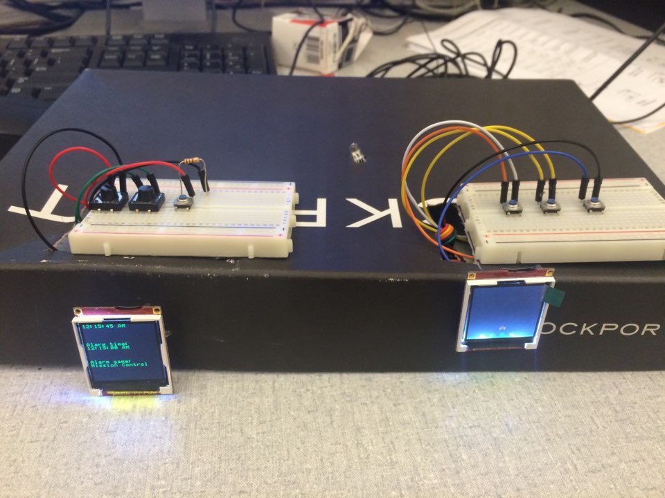
This is the picture of the final alarm clock product.
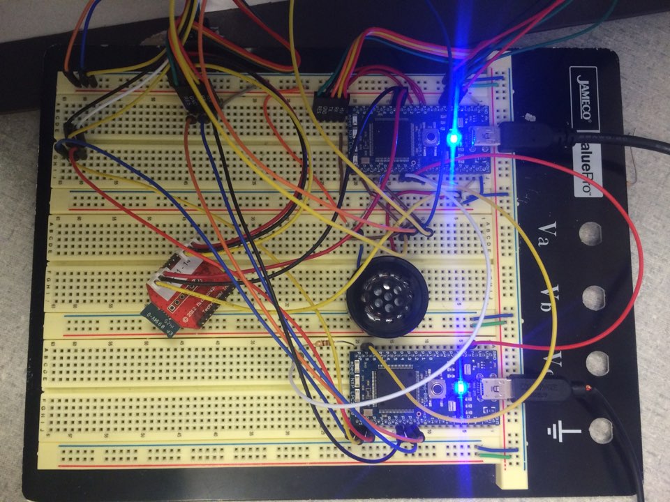
 This is the picture of the circuit found within the alarm clock

Components
Circuits
Time uLCD Connections
| mbed | uLCD |
|---|---|
| Vu | 5V |
| Rx(p10) | Tx |
| Tx(p9) | Rx |
| p11 | Reset |
| GND | GND |
Mission Control uLCD Connections
| mbed | uLCD |
|---|---|
| Vu | 5V |
| Rx(p27) | Tx |
| Tx(p28) | Rx |
| p29 | Reset |
| GND | GND |
Bluetooth Module
| mbed | Bluetooth Module |
|---|---|
| Vu | Vdd (p1) |
| Rx(p27) | Tx(p2) |
| Tx(p28) | Rx(p3) |
| GND | GND(p10) |
Program
Import programalarmClock
Interactive Alarm Clock Code
Import programmissionControlStandalone
Mission Control Code for Interactive Alarm Clock
Please log in to post comments.
