How to external USB receptacle on mbed
<How to connect>
USBを外付けする方法
schematic /media/uploads/suupen/schematic_design__mbed_externalusb.pdf
日本語文章(Japanese script) /media/uploads/suupen/externalusb-japanese-.pdf
External USB receptacle (hereinafter, USB external) D-, D+ is 33 [Ω] through a resistor, IF- the mbed, to connect to the IF +. External USB VBUS ResettableFuse (polyswitch) 500 [mA] terminal of the mbed through the VU.
mbed       Parts                   External USB
VU    Resettble Fuse (500mA)    VBUS
IF-    33 [Ω]                        D-
IF +      33 [Ω]                        D +
GND      direct                        GND
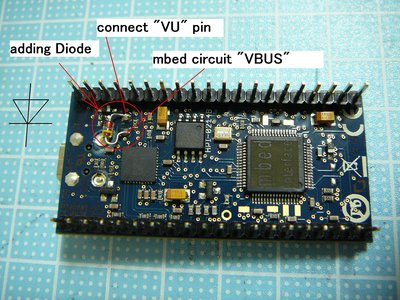
Connect the diode rectifier to the free land near the pin on the back of “nR” mbed. (Photo 1)

Add photo diode to 1 mbed
<Caution>
USB and has been implemented in mbed, USB external can not be used simultaneously.
<Description>
NR terminal side of the free land that is connected to the VU. Land on the opposite side are connected to USB VBUS is implemented mbed. This free pattern is the current limit IC USB (PFP2123) VIN, and is connected to VOUT. In order to supply mbed VBUS power of USB with external power supply originally (5 to pin VU from VBUS in mbed [V] supply) and the reverse, the power supply to the VBUS inside mbed terminal VU File. To put an external USB current limit, between the VU and mbedPin external USB VBUS put Resettable Fuse.
Mbed by supplying to the VBUS from the external USB, you can do the D + pin internal pull-up mbed.
The external USB D-to D + is the short-circuit protection, 33 as noise [Ω]: Add a resistor.
Leave the modification of the above, it is possible to use the USB mbed.
Please log in to post comments.
