This library is for Arduino TFT LCD Screen module.(for new LCD driver IC)
Dependents: ArduinoTFTLCDScreenSample_SPI18TFT
Fork of ST7735_TFT by
いきさつ
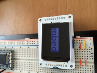
Arduino TFT LCD ScreenというLCD moduleをmbedで使用しました。(module詳細 switch science web)
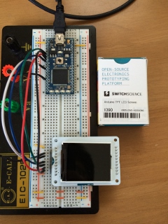
このLCD moduleのLCD driver ICはST7735 ですが、複数のバージョンがあり、libraryとICのバージョンが合わないと正常に表示しません。
mbedにはこのICに対応したlibrary(ST7735_TFT)がありますが、私が入手したLCD moduleではICの種類が違うためか正常に動作しませんでした。幸い、switch scienceのwebにarduino用の対応libraryがあったので、これを元にmbedのlibrary(ST7735_TFT)に移植しました。
libraryの移植
移植元のArduino library
移植元はswitch science webにある置き換え用TFTライブラリ(Arduino IDE1.0.5用)を使用します。このファイルを解凍してできる、"Adfruit_ST7735.cpp"の230行目以降のGcmd[]配列が該当するdriver ICの設定データになります。
Adfruit_ST7735.cpp
・
・
・
  Gcmd[] = {                  // Initialization commands for 7735B screens
    19,                       // 18 commands in list:
    ST7735_SWRESET,   DELAY,  //  1: Software reset, no args, w/delay
      50,                     //     50 ms delay
    ST7735_SLPOUT ,   DELAY,  //  2: Out of sleep mode, no args, w/delay
      100,                    //     255 = 500 ms delay
    0x26 , 1,  			// 3: Set default gamma
      0x04,                     //     16-bit color
    0xb1, 2,              	// 4: Frame Rate
      0x0b,
      0x14,
    0xc0, 2,                    // 5: VRH1[4:0] & VC[2:0]
      0x08,
      0x00,
    0xc1, 1,                    // 6: BT[2:0]
      0x05,
    0xc5, 2,                    // 7: VMH[6:0] & VML[6:0]
      0x41,
      0x30,
    0xc7, 1,                    // 8: LCD Driving control
      0xc1,
    0xEC, 1,                    // 9: Set pumping color freq
      0x1b,
    0x3a , 1 + DELAY,  	        // 10: Set color format
      0x55,                     //     16-bit color
      100,
    0x2a, 4,                    // 11: Set Column Address
      0x00,
      0x00,
      0x00,
      0x7f,
    0x2b, 4,                    // 12: Set Page Address
      0x00,
      0x00,
      0x00,
      0x9f,
    0x36, 1,                    // 12+1: Set Scanning Direction
      0xc8,
    0xb7, 1,			// 14: Set Source Output Direciton
      0x00,
    0xf2, 1,			// 15: Enable Gamma bit
      0x00,
    0xe0, 15 + DELAY,		// 16: magic
      0x28, 0x24, 0x22, 0x31,
      0x2b, 0x0e, 0x53, 0xa5,
      0x42, 0x16, 0x18, 0x12,
      0x1a, 0x14, 0x03,
      50,
    0xe1, 15 + DELAY,		// 17: more magic
      0x17, 0x1b, 0x1d, 0x0e,
      0x14, 0x11, 0x2c, 0xa5,
      0x3d, 0x09, 0x27, 0x2d,
      0x25, 0x2b, 0x3c,
      50,
    ST7735_NORON  ,   DELAY,  // 17: Normal display on, no args, w/delay
      10,                     //     10 ms delay
    ST7735_DISPON ,   DELAY,  // 18: Main screen turn on, no args, w/delay
      255 };                  //     255 = 500 ms delay
・
・
・
移植先のmbed library
移植先となるmbed libraryはST7735_TFT libraryとなります。この中のST7735_TFT.cppのtft_reset() にIC設定データを追加します。追加したコードを区別するため"ST7735B"というdefine定義で条件コンパイルするようにしました。
追加したコードの最後にある"switch(orientation)"の節はarduinoのlibraryにはなく、mbedのlibraryから修正したものです。
ST7735_TFT.cpp
・
・
・
void ST7735_TFT::tft_reset() {
    static unsigned short driverCode;

    // init SPI
    _spi.format(8,3);                 // 8 bit spi mode 3
    _spi.frequency(16000000);         // 16Mhz SPI clock ... 15Mhz is maximum for display, but it seems to work

    // reset exactly like in Arduino version
    _cs = 0;
    _reset = 1;                       // reset
    wait_ms(500);
    _reset = 0;                       // reset
    wait_ms(500);
    _reset = 1;                       // reset
    wait_ms(500);

 #ifdef ST7735B //@ss
    /* Start Initial Sequence ----------------------------------------------------*/
    wr_cmd(ST7735_SWRESET);                         /* SW Reset                       */
    wait_ms(150);
    wr_cmd(ST7735_SLPOUT);                         /* Out of sleepmode               */
    wait_ms(500);

    wr_cmd(0x26);   // 3: Set default gamma
    wr_dat(0x04);   //      16-bit color

    wr_cmd(ST7735_FRMCTR1);                         /*4 Frame rate in normal mode            */
    wr_dat(0x0b);
    wr_dat(0x14);


    wr_cmd(0xc0);   // 5 POWER CONTROL 1
    wr_dat(0x08);
    wr_dat(0x00);

    wr_cmd(0xc1);   // 6 POWER CONTROL 2
    wr_dat(0x05);

    wr_cmd(0xC5);   // POWER CONTROL 6
    wr_dat(0x41);            //
    wr_dat(0x30);

    wr_cmd(0xc7);   // 8:LCD Driving control
    wr_dat(0xc1);

    wr_cmd(0xec);   // 9:Set color format
    wr_dat(0x1b);   //      16-bit color

    wr_cmd(0x3A);   // COLOR MODE
    wr_dat(0x55);            //
    wait_ms(100);

    wr_cmd(0x2a);   // 11 COLUMN ADDR SET
    wr_dat(0x00);   //
    wr_dat(0x00);   // xstart = 0
    wr_dat(0x00);   //
    wr_dat(0x7F);   // xend = 127

    wr_cmd(0x2b);   // ROW ADDR SET
    wr_dat(0x00);   //
    wr_dat(0x00);   // ystart = 0
    wr_dat(0x00);   //
    wr_dat(0x9F);   // yend = 159

    wr_cmd(0x36);   // 13 Set Scanning Direction
    wr_dat(0xc8);

    wr_cmd(0xb7);   // 14 Set Source Output Direction
    wr_dat(0x00);
    /* Gamma settings  -----------------------------------------------------------*/

  wr_cmd(0xE0); // GMCTRP1
  wr_dat(0x28);
  wr_dat(0x24);
  wr_dat(0x22);
  wr_dat(0x31);

  wr_dat(0x2b);
  wr_dat(0x0e);
  wr_dat(0x53);
  wr_dat(0xa5);

  wr_dat(0x42);
  wr_dat(0x16);
  wr_dat(0x18);
  wr_dat(0x12);

  wr_dat(0x1a);
  wr_dat(0x14);
  wr_dat(0x03);

    wait_ms(50);

  wr_cmd(0xE1); // GMCTRN1
  wr_dat(0x17);
  wr_dat(0x1b);
  wr_dat(0x1d);
  wr_dat(0x0e);

  wr_dat(0x14);
  wr_dat(0x11);
  wr_dat(0x2c);
  wr_dat(0xa5);

  wr_dat(0x3d);
  wr_dat(0x09);
  wr_dat(0x27);
  wr_dat(0x2d);

  wr_dat(0x25);
  wr_dat(0x2b);
  wr_dat(0x3c);

    wait_ms(50);

  wr_cmd(0x13); // 18 Normal display on no args.
  wait_ms(10);

  wr_cmd(0x29);  // 19 Main screen turn on, no args.normal display on
  wait_ms(500);

  switch (orientation) {
        case 0:
            wr_reg(0x36, 0x0008);   //originalでの0xc8は間違いで、ST7735_MADCTL(0x36)ではないか
            break;
        case 1:
            wr_reg(0x36, 0x0068);
            break;
        case 2:
            wr_reg(0x36, 0x00C8);
            break;
        case 3:
            wr_reg(0x36, 0x00A8);
            break;
    }

#else //@ss ~ST7735B (original)
   /* Start Initial Sequence ----------------------------------------------------*/
    wr_cmd(ST7735_SWRESET);                         /* SW Reset                       */
    wait_ms(150);
    wr_cmd(ST7735_SLPOUT);                         /* Out of sleepmode               */
    wait_ms(500);
・
・
・
mbed library自体の修正
上記のdriver IC設定値の修正だけでは、LCDの表示領域がずれるなどの不具合がありました。この修正も行います。この不具合の原因が、driver ICの種類の違いよるものなのか、コードそのものの不具合なのかはわかりません。
修正コードは"@ss"のコメントをつけた行になります。
1.driver ICへの画像データバッファアドレス指示の修正
pixel()関数で使用しているwindow()関数の引数が間違っています。元のコードは、終点のx,yが絶対座標形式のようになっていますが、視点からの相対座標を設定しないといけません。
ST7735_TFT.cpp
・
・
・
void ST7735_TFT::pixel(int x, int y, int color) {
  if ((x >= width()) || (y >= height())) return;

    window(x,y,1,1);    //@ss
//@ss  window(x,y,x+1,y+1);

  // setup for data
・
・
・
2.window()関数の座標原点のずれ
driver ICの仕様かもしれませんが、driver ICの画像データバッファの原点が、x=2, y=1となっています。このlibraryで使用される原点はx=0, y=0なので、offsetを追加します。
ST7735_TFT.cpp
・
・
・
void ST7735_TFT::window (unsigned int x, unsigned int y, unsigned int w, unsigned int h) {
    //@ss なぜか CASET(X軸)で2, RASET(Y軸)で1 が最小値になっており、これがLCDDisplayのx,y原点になっていない(LCDの原点を設定するためには(-2,-1)を指示する必要がある
    //@ss プログラム上はLCD原点を0,0にするために、この関数でoffsetをかける。
    x-=2;   //@ss
    y-=1;   //@ss
  wr_cmd(ST7735_CASET);  // column addr set
  wr_dat(0x00);
・
・
・
3.端子定義処理での"orientation"変数の初期値設定タイミングの変更
"ST7735_TFT()"関数内の"orientation"変数の初期値設定がtft_reset()の後になっていますが、tft_reset()内でこの変数を使用しているので、tft_reset()実行前に、変数値を設定する必要があります。
ST7735_TFT.cpp
・
・
・
ST7735_TFT::ST7735_TFT(PinName mosi, PinName miso, PinName sclk, PinName cs, PinName rs, PinName reset, const char *name)
        : _spi(mosi, miso, sclk), _cs(cs), _rs(rs), _reset(reset),GraphicsDisplay(name) {
    orientation = 1;    //@ss
    tft_reset();
//@ss    orientation = 2;
    char_x = 0;
・
・
・
補足:LCD 表示原点の設定
今回使用したmoduleのLCDは160*128ピクセルのものです。画像データの送信によって、x,y軸を入れ替える(横長、縦長)ことができます。これを設定するのが、上記"3"のorientation変数になります。この変数は"set_orientation()"関数の引数として与えることで変更することができます。引数は0,1,2,3となります。
<縦横選択>
0,2 : 縦長(x=0-127, y=0-159)
1,3 : 横長(x=0-159, y=0-127)
<縦(y軸)座標値増加方向>
0,1を基準にした場合、2,3は上下が逆転する
<表示例>
orientation = 0
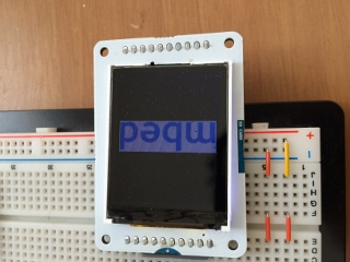
orientation = 1
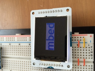
orientation =2
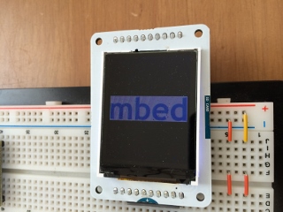
orientation=3
以上
ST7735_TFT.h
- Committer:
- suupen
- Date:
- 2014-09-20
- Revision:
- 2:9a62e159e30c
- Parent:
- 0:246f2fb5be59
File content as of revision 2:9a62e159e30c:
/*
この Libraryは Arduino TFT LCD Screenを使うために"ST7735_TFT"Libraryを改造したものです。
original library からの変更箇所はcomment"//@ss"の行になります。
*/
/* mbed library for 128*160 pixel display TFT based on ST7735 LCD Controller
* ST7735 specific routines (initialization, window addressing, pixel output)
* Copyright (c) 2011 Jonne Valola
*
* WARNING !! WORK IN PROGRESS !!!
*
* Graphics routines and SPI routines derived work used with permission from:
* mbed library for 240*320 pixel display TFT based on HX8347D LCD Controller
* Copyright (c) 2011 Peter Drescher - DC2PD
*
* THE SOFTWARE IS PROVIDED "AS IS", WITHOUT WARRANTY OF ANY KIND, EXPRESS OR
* IMPLIED, INCLUDING BUT NOT LIMITED TO THE WARRANTIES OF MERCHANTABILITY,
* FITNESS FOR A PARTICULAR PURPOSE AND NONINFRINGEMENT. IN NO EVENT SHALL THE
* AUTHORS OR COPYRIGHT HOLDERS BE LIABLE FOR ANY CLAIM, DAMAGES OR OTHER
* LIABILITY, WHETHER IN AN ACTION OF CONTRACT, TORT OR OTHERWISE, ARISING FROM,
* OUT OF OR IN CONNECTION WITH THE SOFTWARE OR THE USE OR OTHER DEALINGS IN
* THE SOFTWARE.
*/
#ifndef MBED_ST7735_TFT_H
#define MBED_ST7735_TFT_H
#include "mbed.h"
#include "GraphicsDisplay.h"
#define RGB(r,g,b) (((r&0xF8)<<8)|((g&0xFC)<<3)|((b&0xF8)>>3)) //5 red | 6 green | 5 blue
#define ST7735B //@SS
/*define ST7735 Commands */
#define ST7735_NOP 0x0
#define ST7735_SWRESET 0x01
#define ST7735_RDDID 0x04
#define ST7735_RDDST 0x09
#define ST7735_SLPIN 0x10
#define ST7735_SLPOUT 0x11
#define ST7735_PTLON 0x12
#define ST7735_NORON 0x13
#define ST7735_INVOFF 0x20
#define ST7735_INVON 0x21
#define ST7735_DISPOFF 0x28
#define ST7735_DISPON 0x29
#define ST7735_CASET 0x2A
#define ST7735_RASET 0x2B
#define ST7735_RAMWR 0x2C
#define ST7735_RAMRD 0x2E
#define ST7735_COLMOD 0x3A
#define ST7735_MADCTL 0x36
#define ST7735_FRMCTR1 0xB1
#define ST7735_FRMCTR2 0xB2
#define ST7735_FRMCTR3 0xB3
#define ST7735_INVCTR 0xB4
#define ST7735_DISSET5 0xB6
#define ST7735_PWCTR1 0xC0
#define ST7735_PWCTR2 0xC1
#define ST7735_PWCTR3 0xC2
#define ST7735_PWCTR4 0xC3
#define ST7735_PWCTR5 0xC4
#define ST7735_VMCTR1 0xC5
#define ST7735_RDID1 0xDA
#define ST7735_RDID2 0xDB
#define ST7735_RDID3 0xDC
#define ST7735_RDID4 0xDD
#define ST7735_PWCTR6 0xFC
#define ST7735_GMCTRP1 0xE0
#define ST7735_GMCTRN1 0xE1
/* some RGB color definitions */
#define Black 0x0000 /* 0, 0, 0 */
#define Navy 0x000F /* 0, 0, 128 */
#define DarkGreen 0x03E0 /* 0, 128, 0 */
#define DarkCyan 0x03EF /* 0, 128, 128 */
#define Maroon 0x7800 /* 128, 0, 0 */
#define Purple 0x780F /* 128, 0, 128 */
#define Olive 0x7BE0 /* 128, 128, 0 */
#define LightGrey 0xC618 /* 192, 192, 192 */
#define DarkGrey 0x7BEF /* 128, 128, 128 */
#define Blue 0x001F /* 0, 0, 255 */
#define Green 0x07E0 /* 0, 255, 0 */
#define Cyan 0x07FF /* 0, 255, 255 */
#define Red 0xF800 /* 255, 0, 0 */
#define Magenta 0xF81F /* 255, 0, 255 */
#define Yellow 0xFFE0 /* 255, 255, 0 */
#define White 0xFFFF /* 255, 255, 255 */
#define Orange 0xFD20 /* 255, 165, 0 */
#define GreenYellow 0xAFE5 /* 173, 255, 47 */
class ST7735_TFT : public GraphicsDisplay {
public:
/** Create a ST7735_TFT object connected to SPI and three pins. ST7735 requires rs pin to toggle between data/command
*
* @param mosi,miso,sclk SPI
* @param cs pin connected to CS of display (called SS for 'Slave Select' in ST7735 datasheet)
* @param rs pin connected to RS of display (called D/CX in ST7735 datasheet)
* @param reset pin connected to RESET of display
*
*/
ST7735_TFT(PinName mosi, PinName miso, PinName sclk, PinName cs, PinName rs, PinName reset,const char* name ="TFT");
/** Get the width of the screen in pixel
*
* @param
* @returns width of screen in pixel
*
*/
virtual int width();
/** Get the height of the screen in pixel
*
* @returns height of screen in pixel
*
*/
virtual int height();
/** Draw a pixel at x,y with color
*
* @param x horizontal position
* @param y vertical position
* @param color 16 bit pixel color
*/
virtual void pixel(int x, int y, int colour);
/** Get colour of pixel at x,y
*
* @param x horizontal position
* @param y vertical position
*/
int getpixel(unsigned int x, unsigned int y);
/** draw a circle
*
* @param x0,y0 center
* @param r radius
* @param color 16 bit color *
*
*/
void circle(int x, int y, int r, int colour);
/** draw a filled circle
*
* @param x0,y0 center
* @param r radius
* @param color 16 bit color *
*
* use circle with different radius,
* can miss some pixel
*/
void fillcircle(int x, int y, int r, int colour);
/** draw a 1 pixel line
*
* @param x0,y0 start point
* @param x1,y1 stop point
* @param color 16 bit color
*
*/
void line(int x0, int y0, int x1, int y1, int colour);
/** draw a rect
*
* @param x0,y0 top left corner
* @param x1,y1 down right corner
* @param color 16 bit color
* *
*/
void rect(int x0, int y0, int x1, int y1, int colour);
/** draw a filled rect
*
* @param x0,y0 top left corner
* @param x1,y1 down right corner
* @param color 16 bit color
*
*/
void fillrect(int x0, int y0, int x1, int y1, int colour);
/** setup cursor position
*
* @param x x-position (top left)
* @param y y-position
*/
void locate(int x, int y);
/** Fill the screen with _backgroun color
*
*/
virtual void cls (void);
/** calculate the max number of char in a line
*
* @returns max columns
* depends on actual font size
*
*/
int columns(void);
/** calculate the max number of columns
*
* @returns max column
* depends on actual font size
*
*/
int rows(void);
/** put a char on the screen
*
* @param value char to print
* @returns printed char
*
*/
int _putc(int value);
/** draw a character on given position out of the active font to the TFT
*
* @param x x-position of char (top left)
* @param y y-position
* @param c char to print
*
*/
virtual void character(int x, int y, int c);
/** paint a bitmap on the TFT
*
* @param x,y : upper left corner
* @param w width of bitmap
* @param h high of bitmap
* @param *bitmap pointer to the bitmap data
*
* bitmap format: 16 bit R5 G6 B5
*
* use Gimp to create / load , save as BMP, option 16 bit R5 G6 B5
* use winhex to load this file and mark data stating at offset 0x46 to end
* use edit -> copy block -> C Source to export C array
* paste this array into your program
*
* define the array as static const unsigned char to put it into flash memory
* cast the pointer to (unsigned char *) :
* tft.Bitmap(10,40,309,50,(unsigned char *)scala);
*/
void Bitmap(unsigned int x, unsigned int y, unsigned int w, unsigned int h,unsigned char *bitmap);
/** paint a 16 bit BMP from local filesytem on the TFT (slow)
*
* @param x,y : upper left corner
* @param *Name_BMP name of the BMP file
* @returns 1 if bmp file was found and painted
* @returns -1 if bmp file was found not found
* @returns -2 if bmp file is not 16bit
* @returns -3 if bmp file is to big for screen
* @returns -4 if buffer malloc go wrong
*
* bitmap format: 16 bit R5 G6 B5
*
* use Gimp to create / load , save as BMP, option 16 bit R5 G6 B5
* copy to internal file system
*
*/
int BMP_16(unsigned int x, unsigned int y, const char *Name_BMP);
/** Read an area from the LCD RAM to MCU RAM
*
* @param x,y : upper left corner
* @param w width of bitmap
* @param h high of bitmap
* @param *buffer pointer to the buffer
*/
void read_area(unsigned int x, unsigned int y, unsigned int w, unsigned int h,unsigned char *buffer);
/** select the font to use
*
* @param f pointer to font array
*
* font array can created with GLCD Font Creator from http://www.mikroe.com
* you have to add 4 parameter at the beginning of the font array to use:
* - the number of byte / char
* - the vertial size in pixel
* - the horizontal size in pixel
* - the number of byte per vertical line
* you also have to change the array to char[]
*
*/
void set_font(unsigned char* f);
/** Set the orientation of the screen
* x,y: 0,0 is always top left
*
* @param o direction to use the screen (0-3) 90� Steps
*
*/
void set_orientation(unsigned int o);
SPI _spi;
DigitalOut _cs;
DigitalOut _rs;
DigitalOut _reset;
unsigned char* font;
protected:
/** draw a horizontal line
*
* @param x0 horizontal start
* @param x1 horizontal stop
* @param y vertical position
* @param color 16 bit color
*
*/
void hline(int x0, int x1, int y, int colour);
/** draw a vertical line
*
* @param x horizontal position
* @param y0 vertical start
* @param y1 vertical stop
* @param color 16 bit color
*/
void vline(int y0, int y1, int x, int colour);
/** Set draw window region
*
* @param x horizontal position
* @param y vertical position
* @param w window width in pixel
* @param h window height in pixels
*/
void window (unsigned int x, unsigned int y, unsigned int w, unsigned int h);
/** Set draw window region to whole screen
*
*/
void WindowMax (void);
/** Init the ST7735 controller
*
*/
void tft_reset();
/** Write data to the LCD controller
*
* @param dat data written to LCD controller
*
*/
void wr_dat(int value);
/** Write a command the LCD controller
*
* @param cmd: command to be written
*
*/
void wr_cmd(int value);
/** Start data sequence to the LCD controller
*
*/
void wr_dat_start();
/** Stop of data writing to the LCD controller
*
*/
void wr_dat_stop();
/** write data to the LCD controller
*
* @param data to be written
* *
*/
void wr_dat_only(unsigned short dat);
/** Read data from the LCD controller
*
* @returns data from LCD controller
*
*/
unsigned short rd_dat(void);
/** Write a value to the to a LCD register
*
* @param reg register to be written
* @param val data to be written
*/
void wr_reg (unsigned char reg, unsigned short val);
/** Read a LCD register
*
* @param reg register to be read
* @returns value of the register
*/
unsigned short rd_reg (unsigned char reg);
unsigned int orientation;
unsigned int char_x;
unsigned int char_y;
};
#endif
