SparkFun MEMS Microphone Breakout - INMP401 (ADMP401)
Overview
This wikipage is designed to give users an understanding of how to use the SparkFun MEMS microphone with the mbed platform. Using a $10 chip from Sparkfun allows one to build a recording device by interfacing with the mbed platform. Since the chip is provided on an IC breakout board it can be directly wired to the mbed without the need for an additional circuit to control the chip output. This allows for quick development time and saves cost, especially useful for prototyping. An example code is given to show users how to implement simple recording and playback functionality. A YouTube video is also provided as a live demo for the user.
Click here to order the MEMS microphone from Sparkfun.
Click here for the datasheet.
Using a Microphone for Analog Input
In order to input an accurate Analog Output into the mbed, Vcc should be connected to 3.3V and the microphone AUD output will float at one half Vcc when there is no sound. The amplifier on the chip has a gain of 67 and produces a peak-to-peak output of 200mV when the microphone is spoken into at arms length at normal conversation levels.
Wiring
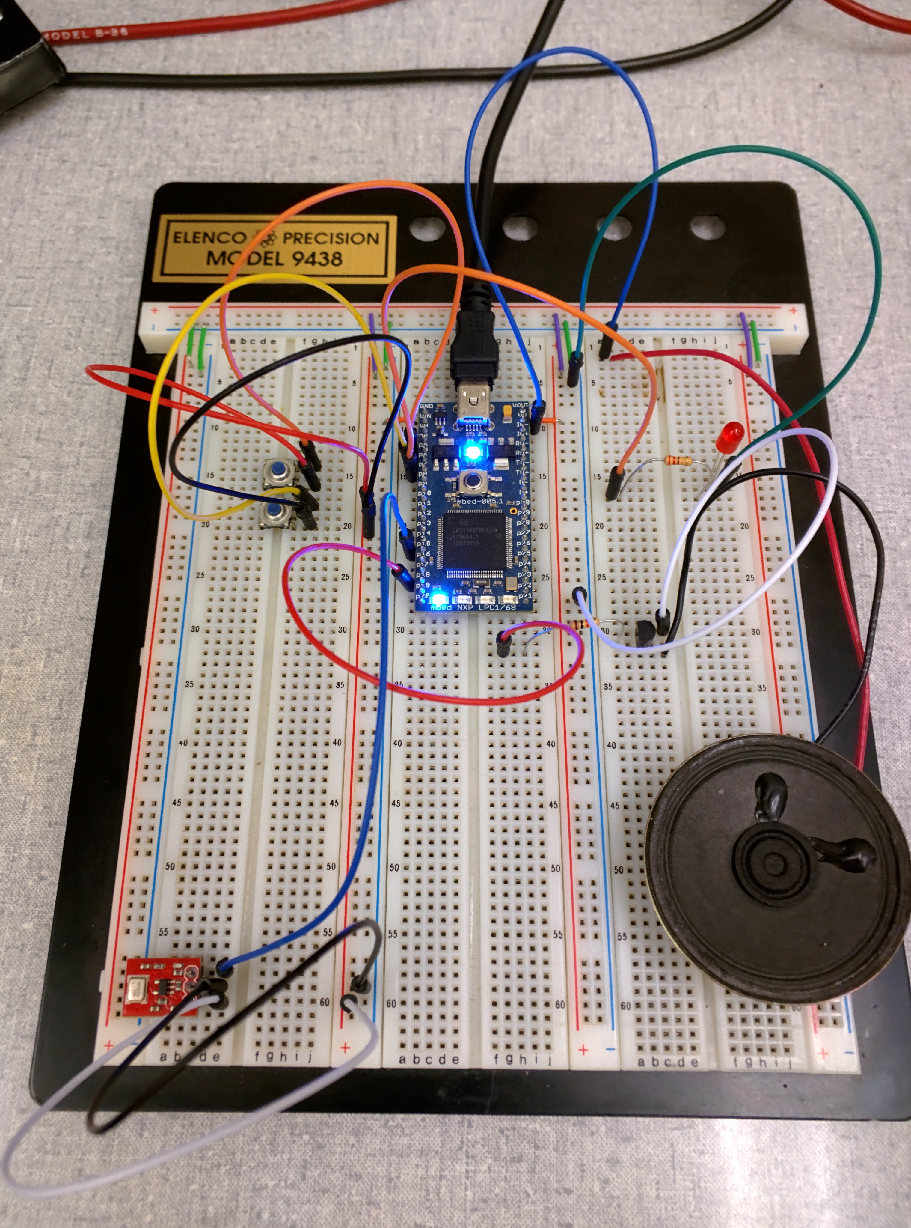
Table 1 describes how to wire the microphone to the mbed. In additon Table 2 displays the connections between the speaker, the record button, and playback button are connected to the mbed. See the linked pages in the demo section for more information on how to hook up these components.
| Microphone | MBED |
|---|---|
| aud | p15 (AnalogIn) |
| gnd | gnd |
| Vcc | VOUT (3.3V) |
Table 1: A table showing how to connect the microphone to the mbed.
| Component | MBED |
|---|---|
| Speaker | p18 (AnalogOut) |
| Record Button | p5 |
| Play Button | p6 |
| Red LED | p7 |
Table 2: A table showing proper connections between the mbed, speaker, record button, play button and LED.
Schematics
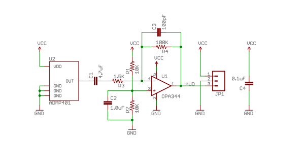
Figure 1 is a schematic [1] of the MEMS chip that produces microphone functionality. Since the microphone is connected to other parts on a breakout board, wiring the microphone to the mbed is simple. It is possible to increase the sensitivity of the microphone by adding more resistors in series with the connection to the mbed.

Figure 1: A schematic of the MEMS chip. [1]
Demo
The following demo records the input from the microphone for one second when the recording push button is pressed. The audio on the speaker is played back when the playback push button is pressed. A red LED lights up when recording, and the on-board mbed LEDs light up depending on the volume of the sound detected.
The following components are required for the demo:
- Two Parallax Pushbutton [2]
- One Speaker [3]
- One Red LED (see example four) [4]
- One SparkFun MEMS Microphone [5]
Code
Provided below is code that sets up interfacing between the microphone and mbed in an easy to use C++ class.
#include "mbed.h"

AnalogIn mic(p15); //microphone input
AnalogOut speaker(p18); //speaker output

DigitalOut led1(LED1); // following leds are used to visualy show amplitude of sound
DigitalOut led2(LED2);
DigitalOut led3(LED3);
DigitalOut led4(LED4);
DigitalOut red(p7);   //this powers a red LED that lights up when recording


DigitalIn pbRec(p5); //pushbutton inputs to either begin recording or playback
DigitalIn pbPlay(p6);

void record(float* sampleArr) {
    //record sound for 1 second
    for(int i=0; i<8000; i++) {
        sampleArr[i] = mic.read(); //put samples in array
        wait(0.000125f); //sample rate of 8000 Hz
    }
}

void play(float* sampleArr) {
    //playback recorded sound
    wait(0.1);
    for(int i=0; i<8000; i++) {
        speaker = sampleArr[i];
        wait(0.000125f);
    }
}

void volume(){
    //the following lights up the onboard LEDs depending on the amplitude of sound
    led1 = (mic > 0.5f) ? 1 : 0;
    led2 = (mic > 0.6f) ? 1 : 0;
    led3 = (mic > 0.7f) ? 1 : 0;
    led4 = (mic > 0.8f) ? 1 : 0;
}

int main() {
    float sampleArr[8000]; //used to store sound
    pbRec.mode(PullDown); //use internal resistors for pushbuttons
    pbPlay.mode(PullDown);
    red = 0;
    while(1){
        volume();

        if (pbRec == 1) {
            wait(0.2);
            red = 1;
            record(sampleArr);
            red = 0;
        }

        if (pbPlay == 1) {
            play(sampleArr);
        }
    }
}
SetUp

Figure 2: A figure showing a properly wired circuit.
Live Demo
Conclusion
This page discussed how to use the MEMS microphone to interface with the mbed to implement simple record playback functionality. The most pertinent problem with the posted demo is the maximum recording time of one second. It would be beneficial to improve this functionality. The problem of such a limited recording time arises from the limited storage space on the mbed. A possible implementation would be to connect an SD card to the mbed, allowing for more storage. This solution might also improve the quality of the recording as more samples could be used to store the information. Another useful improvement would be to convert the code into a library. This would allow newer users to make calls to functions in the provided code inside of the user's program. In addition, it would be possible for the the library to be maintained by the mbed community.
References
[1] https://www.sparkfun.com/datasheets/BreakoutBoards/ADMP401-Breakout-v13.pdf
[2] https://developer.mbed.org/users/4180_1/notebook/pushbuttons/?compage=1#c6483
[3] https://developer.mbed.org/users/4180_1/notebook/using-a-speaker-for-audio-output/
[4] https://developer.mbed.org/users/yoonghm/notebook/digital-output/
[5] https://www.sparkfun.com/products/9868
Please log in to post comments.
