This is a basic MBED driver for the AD9850 digital sine wave synthesizer. It uses a hacked SPI interface to drive the device,
I was looking for a way to test the frequency response of a new oscilloscope.
Analog Devices has a nice IC that can produce a digitally synthesized sine wave of frequency between 0 and about 70 MHz. AD9850 link is here: http://www.analog.com/en/rfif-components/direct-digital-synthesis-dds/ad9850/products/product.html
What made things even easier was the availability of ready-to-go evaluation boards from China on Ebay for less than $5.
This is the one I got:
This design is limited to about 40MHz if you want a clean signal without aliasing.
Frequency and phase are set by a 40-bit command that has:
- 32-bit frequency setting
- 5-bit phase setting
- 1-bit power up/down
- 2-bits factory debug access

Output frequency is given by: fOUT = (frq × CLKIN)/(2^32)
where frq is the 32-bit frequency and CLKIN is the frequency of the on-board crystal (125MHz in this case) So, for example 0x147AE148 is 10MHz.
Frequency resolution has a step size of 29KHz with the 125MHz clock.
You can also change phase in increments of 180°, 90°, 45°, 22.5°, 11.25° or any combination thereof using the 5-bit phase command. However I didn't implement this and left phase as zero.
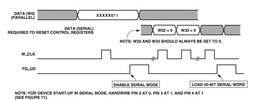
I used a serial interface from the LPC1768 MBED to the AD9850 board as I didn't want to be bothered with all the wiring of a parallel bus. The required timing looks like this:

This looks quite like an SPI interface. Much easier to use the LPC's SPI block than to do bit-banging.
AD9850 wants low base clock state and clock falling edge data latching which adds up to SPI mode 0.
Only significant difference to SPI is the FQ_UD (frequency update) command. This looks quite like SPI's chip select line except using positive logic. Can use a GPIO line to fake that.
The other hacks that are required are:
(1) MBED SPI limits the bits per packet to 16. Work around is to use 2 x 16-bit packets and then 1 x 8-bit packet. Another benefit of directly controlling the CS signal with a GPIO line is that CS can be kept low even between the 3 packets required to make up the 40-bits. Normally an SPI block would automatically take CS high again.
(2) Even though the LPC allows for setting LSB or MSB first, MBED only provides for MSB first whereas the AD9850 wants LSB first. Could work around that by writing a direct driver for the LPC. However I thought it was simpler just to write a function that swaps bit 31 with bit 0, bit 30 with bit 1 etc. High performance SPI isn't needed so that is the simplest solution. There are bit swapping algorithms out there, however they are made for single bytes.
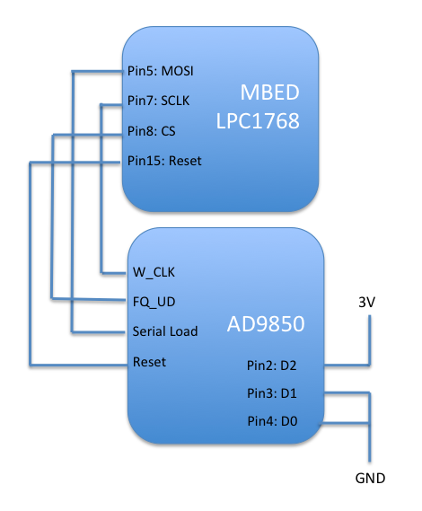
Connection of the boards is like this:


D2-D0 are hardwired 1,0,0 to force the AD9850 into serial mode. The AD9850 board is powered at 3V since this is the MBED GPIO voltage.
I used a Saleae Logic logic analyzer to watch the signals

This shows the 3 packets that make up the 40-bit command. Luckily the AD9850 only specifies the minimum time between bits; there doesn't seem to be a maximum as long as the next FQ_UD pulse does not arrive.
Code loops from 10MHz to 20MHz and back down again.

Diff: main.cpp
- Revision:
- 0:b5fb7b3adfe2
- Child:
- 1:b0e6c82af2ef
--- /dev/null	Thu Jan 01 00:00:00 1970 +0000
+++ b/main.cpp	Sat Sep 28 04:32:20 2013 +0000
@@ -0,0 +1,90 @@
+// MBED driver for AD9850 digital synthesizer using hacked SPI interface
+// Liam Goudge Sept 2013
+
+#include "mbed.h"
+
+SPI device (p5,p6,p7); // MOSI, MISO (not used), SCLK
+DigitalOut CS(p8); // Use pin 8 as a fake Chip select
+DigitalOut ADReset(p15); // Pin 15 is reset line for AD9850
+
+Serial pc(USBTX, USBRX); // tx, rx for debug terminal
+
+int reverseBits (int source)
+{
+// Unfortunately need to invert bit order of the desired frequency setting since MBED only allows for MSB first from SPI. We need LSB first for AD9850
+    int mask=0;;
+    int i=0;
+    int target=0;
+    int bitTarget=0x80000000; // Hard-wired for 32-bit inversion
+
+    for (i=0;i<32;i++) { // ditto
+        mask=1<<i;
+        bitTarget=1<<(31-i); // ditto
+
+        if (source & mask)
+            target=target | bitTarget;
+    }
+    return target;
+}
+
+void writeSPI(int frq, int phase)
+{
+// Send the 40-bit packet. MBED only allows max 16-bit packets so we send 40-bits as 16, 16, 8
+    device.format(16,0); // 16-bits per packet, mode 0 (CPOL=0 CPHA=0)
+    device.frequency(1000000); //SPI clock set to 1MHz
+
+    wait_ms(5);
+
+    // First do chip select. Need to use a GPIO to fake the chip select since MBED doesn't allow to set positive logic CS signal
+    CS=1; // assert chip select (a.k.a FQ_UD frequency update input to AD9850)
+    wait_ms(5);
+    CS=0;
+
+    device.write(frq>>16); // Write upper 16-bits first starting with bit 31
+    device.write(frq); // Now lower 16 bits starting with bit 15
+
+    device.format(8,0); // Need to reset to 8-bit data since MBED only allows max 16-bit packets. For 40-bits we do 16, 16, 8
+    device.write(phase); // This is phase and factory settings byte
+
+    // Now pulse FQ_UD again to signal the end of the packet
+    CS=0;
+    wait_ms(5);
+    CS=1;
+    wait_ms(5);
+    CS=0;
+}
+
+
+int main()
+{
+    int targetFrq=0x147AE148; // This is desired sine wave frequency for the AD9850, here set to 10MHz
+    int increment=0x346DC6; // This is a 100KHz frequency increment
+
+    // Reset the AD9850. Active high logic. Minimum reset period 5 clock cycles (5/125MHz)
+    ADReset=0;
+    wait_ms(5);
+    ADReset=1;
+    wait_ms(5);
+    ADReset=0;
+
+    while(1)
+    {
+
+    while (targetFrq<0x28F5C28F) // 20MHz
+    {
+        writeSPI(reverseBits(targetFrq),0);
+        targetFrq=targetFrq+increment;
+        //wait_ms(100);
+        }
+
+    while (targetFrq>0x147AE148) // 10MHz
+    {
+        writeSPI(reverseBits(targetFrq),0);
+        targetFrq=targetFrq-increment;
+        //wait_ms(100);
+        }
+
+    }
+
+
+}
\ No newline at end of file