The official mbed C/C SDK provides the software platform and libraries to build your applications.
Fork of mbed by
(01.May.2014) started sales! http://www.switch-science.com/catalog/1717/
(13.March.2014) updated to 0.5.0
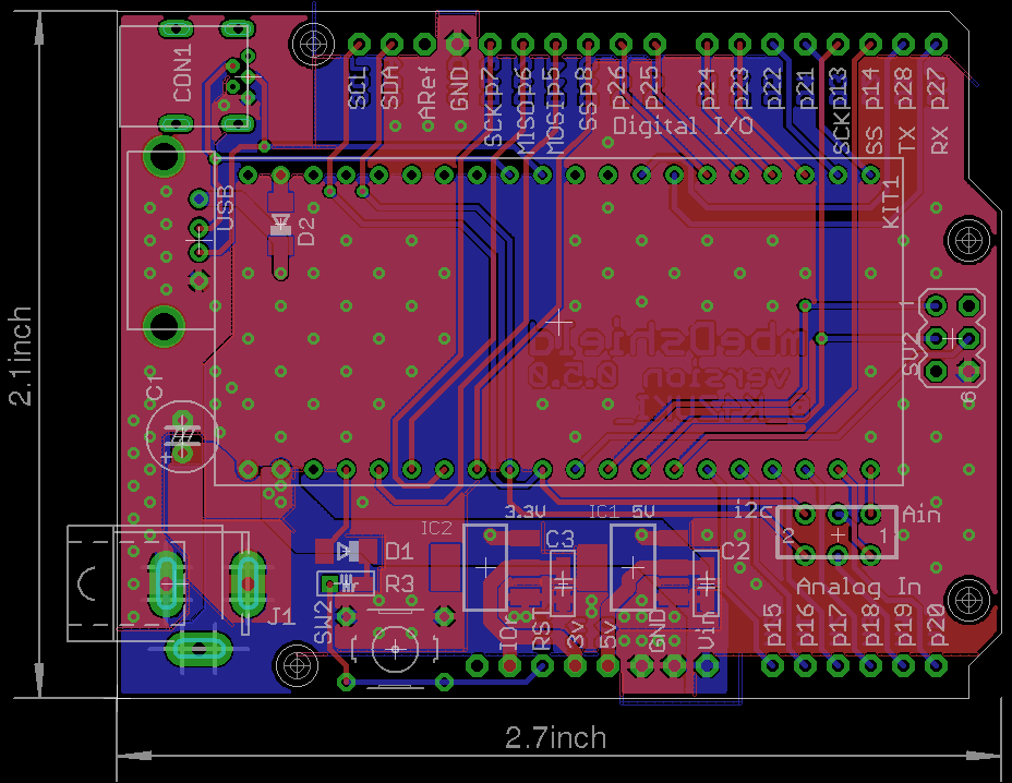
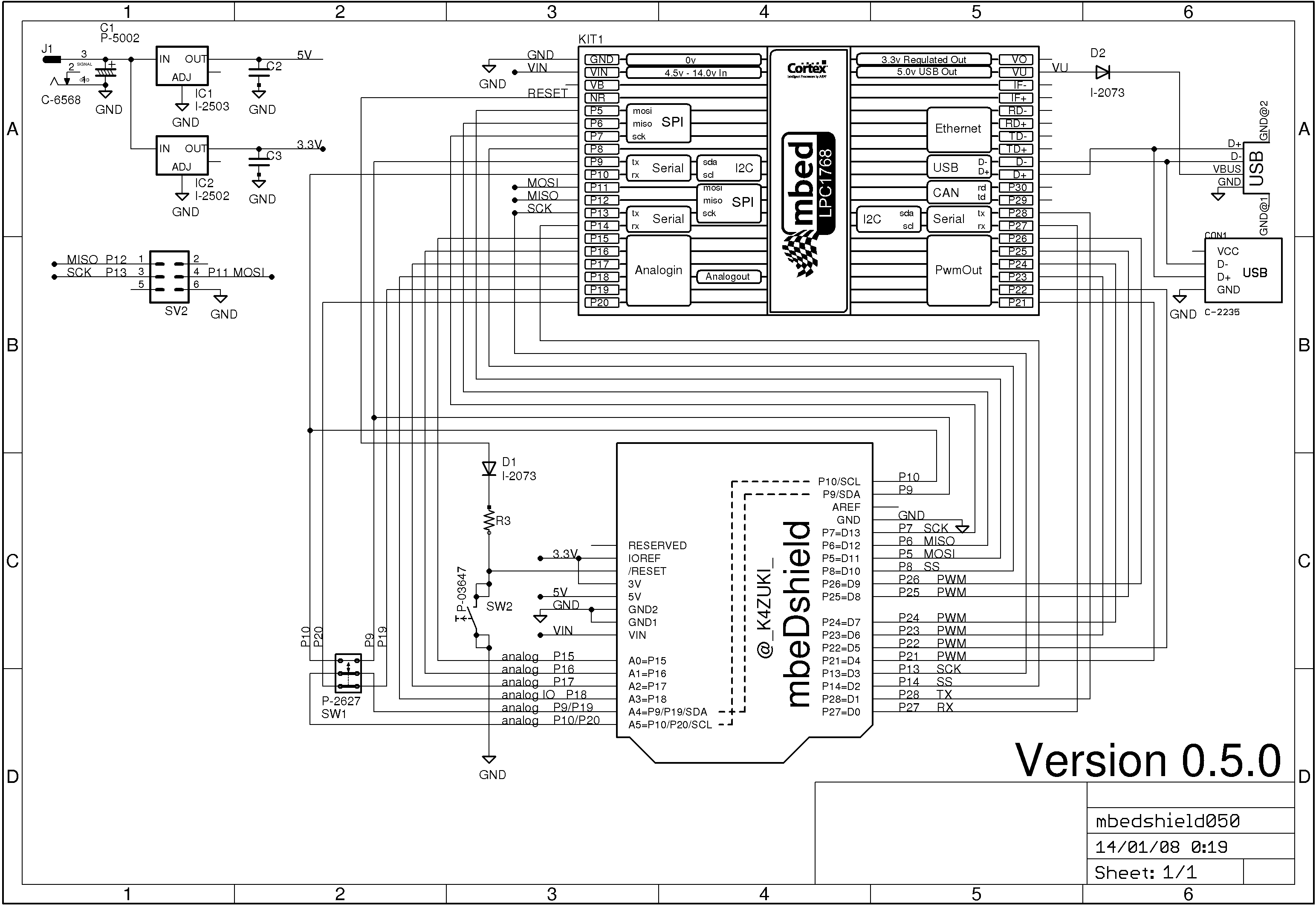
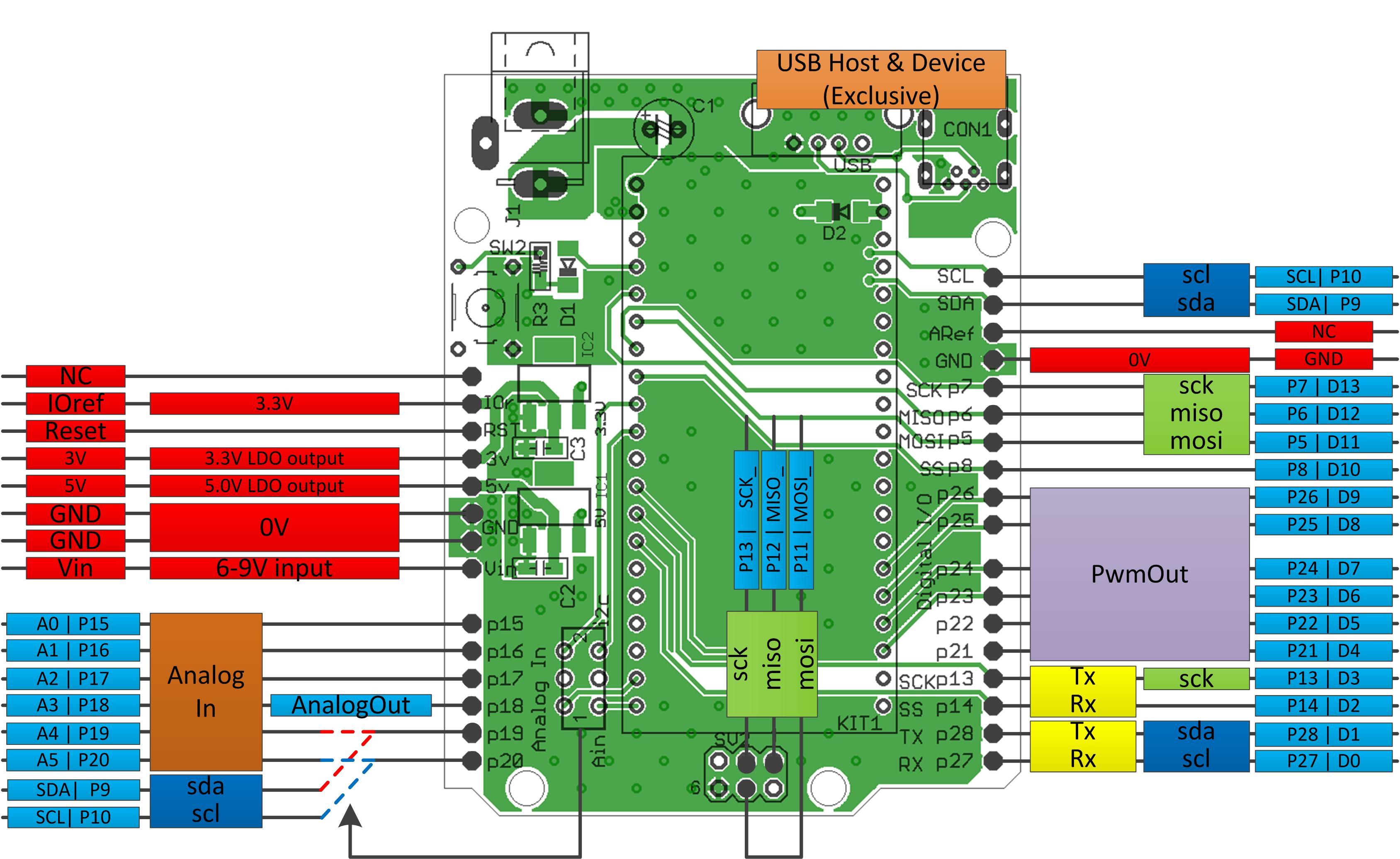
This is a pin conversion PCB from mbed 1768/11U24 to arduino UNO.
- So if you have both mbed and arduino shields, I guess you would be happy with such a conversion board :)
Photos
- Board photo vvv

- Schematic photo vvv

- Functionality photo vvv

Latest eagle files
PCB >> /media/uploads/k4zuki/mbedshield050.brd
SCH >> /media/uploads/k4zuki/mbedshield050.sch
BIG changes from previous version
- Ethernet RJ45 connector is removed.
- http://mbed.org/components/Seeed-Ethernet-Shield-V20/ is the biggest hint to use Ethernet!
MostALL of components can be bought at Akizuki http://akizukidenshi.com/- But sorry, they do not send parts to abroad
- Pinout is changed!
| arduino | 0.4.0 | 0.5.0 |
|---|---|---|
| D4 | p12 | p21 |
| D5 | p11 | p22 |
| MOSI_ | none | p11 |
| MISO_ | none | p12 |
| SCK_ | none | p13 |
This design has bug(s)
- I2C functional pin differs between 1768 and 11U24.
Fixed bugs here
- MiniUSB cable cannot be connected on mbed if you solder high-height electrolytic capacitor on C3.
- http://akizukidenshi.com/catalog/g/gP-05002/ is the solution to make this 100% AKIZUKI parts!
- the 6-pin ISP port is not inprimented in version 0.4.0
it will be fixed in later version 0.4.1/0.4.2/0.5.0This has beenfixed
I am doing some porting to use existing arduino shields but it may faster if you do it by yourself...
you can use arduino PinName "A0-A5,D0-D13" plus backside SPI port for easier porting.
To do this you have to edit PinName enum in
- "mbed/TARGET_LPC1768/PinNames.h" or
- "mbed/TARGET_LPC11U24/PinNames.h" as per your target mbed.
here is the actual list: This list includes define switch to switch pin assignment
part_of_PinNames.h
        USBTX = P0_2,
        USBRX = P0_3,

//from here mbeDshield mod
        D0=p27,
        D1=p28,
        D2=p14,
        D3=p13,
#ifdef MBEDSHIELD_050
        MOSI_=p11,
        MISO_=p12,
        SCK_=p13,
        D4=p21,
        D5=p22,
#else
        D4=p12,
        D5=p11,
#endif
        D6=p23,
        D7=p24,
        D8=p25,
        D9=p26,
        D10=p8,
        D11=p5,
        D12=p6,
        D13=p7,
        A0=p15,
        A1=p16,
        A2=p17,
        A3=p18,
        A4=p19,
        A5=p20,
        SDA=p9,
        SCL=p10,
//mbeDshield mod ends here
        // Not connected
        NC = (int)0xFFFFFFFF
Diff: SPI.h
- Revision:
- 11:1c1ebd0324fa
- Parent:
- 5:62573be585e9
- Child:
- 20:029aa53d7323
--- a/SPI.h	Thu May 14 14:44:00 2009 +0000
+++ b/SPI.h	Fri Aug 28 12:10:11 2009 +0000
@@ -1,108 +1,107 @@
-/* mbed Microcontroller Library - SPI
- * Copyright (c) 2006-2009 ARM Limited. All rights reserved.
- * sford
- */
-
-#ifndef MBED_SPI_H
-#define MBED_SPI_H
-
-#include "Base.h"
-#include "LPC2300.h"
-
-namespace mbed {
-
-/* Class: SPI
- *  A SPI Master, used for communicating with SPI slave devices
- *
- * The default format is set to 8-bits, mode 0, and a clock frequency of 1MHz
- *
- * Most SPI devices will also require Chip Select and Reset signals. These
- * can be controlled using <DigitalOut> pins
- *
- * Example:
- * > // Send a byte to a SPI slave, and record the response
- * >
- * > #include "mbed.h"
- * >
- * > SPI device(5, 6, 7); // mosi, miso, sclk
- * >
- * > int main() {
- * >     int response = device.write(0xFF);
- * > }
- */
-class SPI : public Base {
-
-public:
-
-	/* Constructor: SPI
-	 *  Create a SPI master connected to the specified pins
-	 *
-	 * Variables:
-	 *  mosi - SPI Master Out, Slave In pin
-	 *  miso - SPI Master In, Slave Out pin
-	 *  sclk - SPI Clock pin
-     *  name - (optional) A string to identify the object
-     *
-	 * Pin Options:
-	 *  (5, 6, 7) or (11, 12, 13)
-	 *
-	 *  mosi and miso can each be specfied as NC (not connected) e.g. (5, NC, 7)
-	 */
-	SPI(int mosi, int miso, int sclk, const char *name = NULL);
-
-	/* Function: format
-	 *  Configure the data transmission format
-	 *
-	 * Variables:
-	 *  bits - Number of bits per SPI frame (4 - 16)
-	 *  mode - Clock polarity and phase mode (0 - 3)
-     *
- 	 * > mode | POL PHA
-     * > -----+--------
-     * >   0  |  0   0
-	 * >   1  |  0   1
-     * >   2  |  1   0
-	 * >   3  |  1   1
-	 */
-	void format(int bits, int mode = 0);
-
-    // old one, to be removed over time...
-	void format(int bits, int polarity, int phase) __attribute__((deprecated));
-
-	/* Function: frequency
-	 *  Set the bus clock frequency
-	 *
-	 * Variables:
-	 *  hz - SCLK frequency in hz (default = 1MHz)
-	 */
-	void frequency(int hz = 1000000);
-
-	/* Function: write
-	 *  Write to the SPI Slave and return the response
-	 *
-     * Variables:
-     *  value - Data to be sent to the SPI slave
-     *  returns - Response from the SPI slave
-	 */
-  	int write(int value);
-
-    virtual const struct rpc_method *get_rpc_methods();
-    static struct rpc_class *get_rpc_class();
-
-protected:
-
-	void configure();
-
-	int _id;
-
-	int _uid;
-	static int _uidcounter;
-
-	int _bits, _polarity, _phase, _hz;
-	static int _config[2];
-};
-
-}
-
-#endif
-
+/* mbed Microcontroller Library - SPI
+ * Copyright (c) 2006-2009 ARM Limited. All rights reserved.
+ * sford
+ */
+
+#ifndef MBED_SPI_H
+#define MBED_SPI_H
+
+#include "platform.h"
+#include "PinNames.h"
+#include "PeripheralNames.h"
+#include "Base.h"
+
+namespace mbed {
+
+/* Class: SPI
+ *  A SPI Master, used for communicating with SPI slave devices
+ *
+ * The default format is set to 8-bits, mode 0, and a clock frequency of 1MHz
+ *
+ * Most SPI devices will also require Chip Select and Reset signals. These
+ * can be controlled using <DigitalOut> pins
+ *
+ * Example:
+ * > // Send a byte to a SPI slave, and record the response
+ * >
+ * > #include "mbed.h"
+ * >
+ * > SPI device(p5, p6, p7); // mosi, miso, sclk
+ * >
+ * > int main() {
+ * >     int response = device.write(0xFF);
+ * > }
+ */
+class SPI : public Base {
+
+public:
+
+    /* Constructor: SPI
+     *  Create a SPI master connected to the specified pins
+     *
+     * Variables:
+     *  mosi - SPI Master Out, Slave In pin
+     *  miso - SPI Master In, Slave Out pin
+     *  sclk - SPI Clock pin
+     *  name - (optional) A string to identify the object
+     *
+     * Pin Options:
+     *  (5, 6, 7) or (11, 12, 13)
+     *
+     *  mosi or miso can be specfied as NOT_CONNECTED if not used
+     */
+    SPI(PinName mosi, PinName miso, PinName sclk, const char *name = NULL);
+
+    /* Function: format
+     *  Configure the data transmission format
+     *
+     * Variables:
+     *  bits - Number of bits per SPI frame (4 - 16)
+     *  mode - Clock polarity and phase mode (0 - 3)
+     *
+     * > mode | POL PHA
+     * > -----+--------
+     * >   0  |  0   0
+     * >   1  |  0   1
+     * >   2  |  1   0
+     * >   3  |  1   1
+     */
+    void format(int bits, int mode = 0);
+
+    /* Function: frequency
+     *  Set the spi bus clock frequency
+     *
+     * Variables:
+     *  hz - SCLK frequency in hz (default = 1MHz)
+     */
+    void frequency(int hz = 1000000);
+
+    /* Function: write
+     *  Write to the SPI Slave and return the response
+     *
+     * Variables:
+     *  value - Data to be sent to the SPI slave
+     *  returns - Response from the SPI slave
+    */
+    int write(int value);
+
+#ifdef MBED_RPC
+    virtual const struct rpc_method *get_rpc_methods();
+    static struct rpc_class *get_rpc_class();
+#endif
+
+protected:
+
+	SPIName _spi;
+
+	void aquire();
+    static SPI *_owner;
+    int _bits;
+    int _mode;
+    int _hz;
+
+};
+
+} // namespace mbed
+
+#endif
