Control of a wheeled robot using Wifly module
General Description This project aims to control a wheeled robot over a RJ45 ethernet connection or a Wifi connection using a Wifly network module. The two DC motors are driven by vnh3sp30 H-bridge drivers. A client computer would use a PHP front-end UI to send commands in UDP packets to the mbed board through the ethernet interface.
Ethernet UDP code A thread was used to set up the Ethernet connection on the mbed and get an IP address. If the connection was successful, the current date and time along with the MAC and IP address assigned to the mbed will be displayed on the TextLCD screen. Next the mbed's IP address can be set as the a target IP address in the PHP user interface. This enables the client running the PHP GUI to send commands to the mbed using a UDP sockets.
The mbed will use the 4th element of a the UDP packet to determine the command to be sent to the two H-bridges that run the left and right motors. For example, Depending on whether buffer[4] is a '+' or '-', the speed of both motors is either increased or decreased by 10%, if buffer[4] is set to 'B', 'L' or 'R', the motors will be stopped, make the robot turn right, left or move in the current direction at full speed, respectively.
Interfacing with the mbed
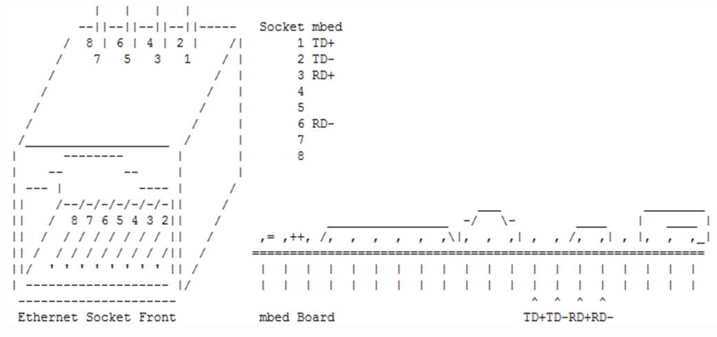
The sparkfun breakout board for the RJ45 Ethernet MDI Jack was used with the following pin mappings between the mbed and the Ethernet adapter.

| Mbed | Ethernet MDI adapter | |||
|---|---|---|---|---|
| TD+ | P1 | |||
| TD- | P2 | |||
| RD+ | P7 | |||
| RD- | P8 |


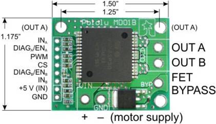
The pinout mappings for each of the two H-bridge drivers and the DC motors are as follows:
| Mbed | H-bridge | Power supply | Motor | |||||
|---|---|---|---|---|---|---|---|---|
| Vu | +5V (IN) | |||||||
| GND | GND | |||||||
| rev | IN_B | |||||||
| fwd | IN_A | |||||||
| Pull high | EN_A | |||||||
| Pull high | EN_B | |||||||
| pwm | PWM | |||||||
| + motor supply | + power supply | |||||||
| GND | - motor supply | Ground of power supply | ||||||
| OUT A | Motor wire 1 | |||||||
| OUT B | Motor wire 2 |
Specifically, for motor 1: p21, p7, p8 represented the pwm, fwd, rev pins on the mbed and for motor 2, p22, p5, p6; represented the pwm, fwd, rev pins on the mbed.
Finally the pinout mappings for the TextLCD screen is as follows:
| Mbed pins | GND | 5V | GND via 1k resistor | p15 | GND | p16 | p17 | p18 | p19 | p20 | ||||||||||||
|---|---|---|---|---|---|---|---|---|---|---|---|---|---|---|---|---|---|---|---|---|---|---|
| TextLCD pins | GND | VCC | VO | RS | RW | E | D4 | D5 | D6 | D7 |
Wifly RN-131G is an 802.11G networking module which we used to connect to GTother network of Georgia Tech. There are several mobile wireless applications of this module so by following this page for the correct connections and configuration, one will be able to do a lot of cool stuff with this module.
Please log in to post comments.
