https://os.mbed.com/handbook/MIDI-Controller-for-Guitar-Players
MIDI Controller for Guitar Players
Team Members: John Jones, John Mikrut
Introduction
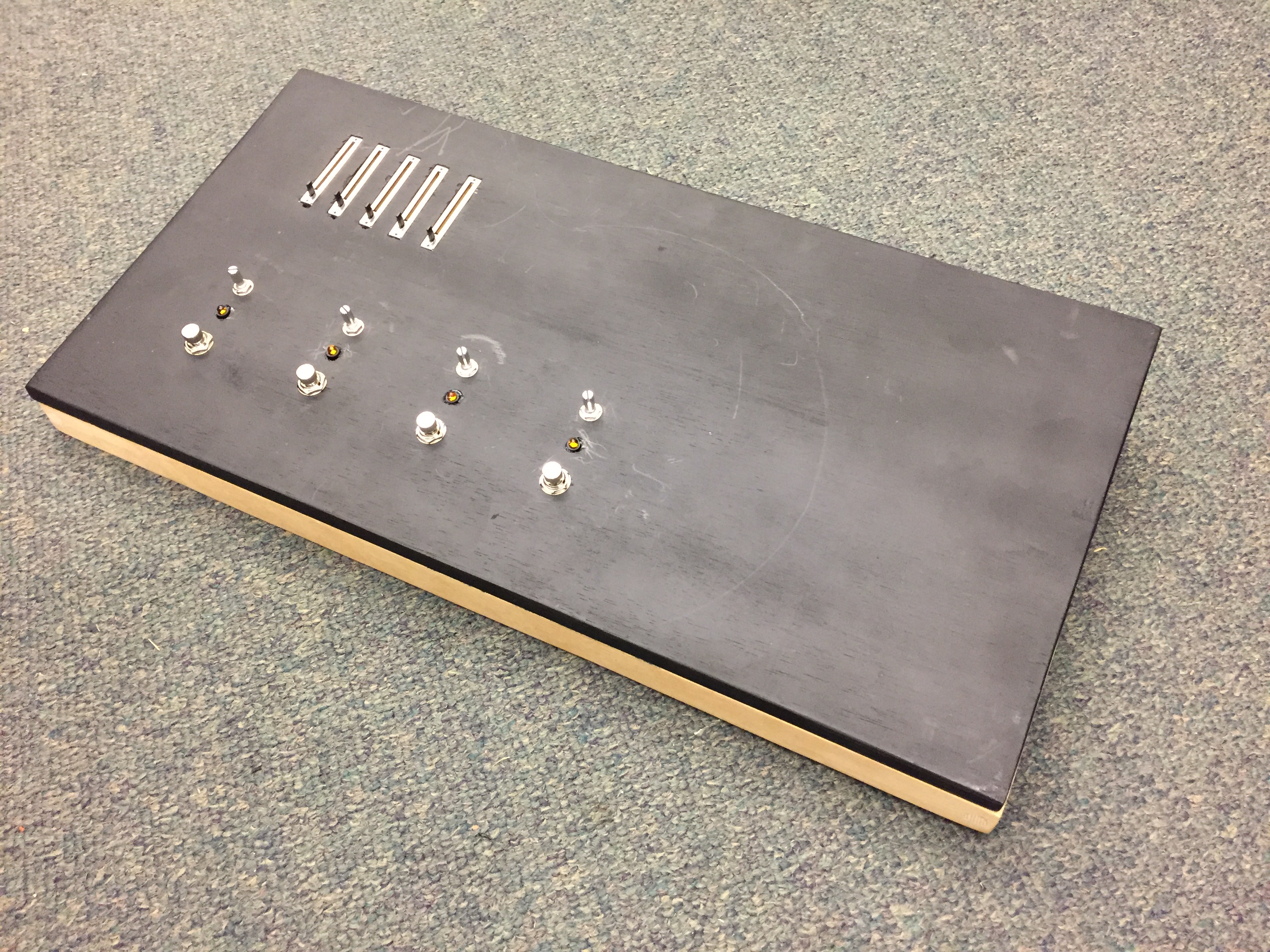
Most guitar players want to add sound effects to their guitar's signal chain, however new amplifiers or effects pedals can be expensive, especially for us humble bedroom players. Guitar players can use software like the Guitar Rig 5 to emulate countless guitar pedals and amplifiers. And although the Guitar Rig 5 demo is great for experimenting with effects and virtual amplifiers, it is difficult to manipulate mid-song while simultaneously playing the instrument. MIDI controllers can solve this problem. Guitar Rig 5 along with most other musician-oriented software applications are designed to respond to MIDI messages to interact with a MIDI controller. We created a MIDI controller that guitar players can use with their feet. As far as we know at the time of writing this documentation, this is the first DIY midi controller that utilizes two microprocessors (one is effectively an analog input mux).
Parts Used
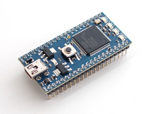
- 1 x Mbed
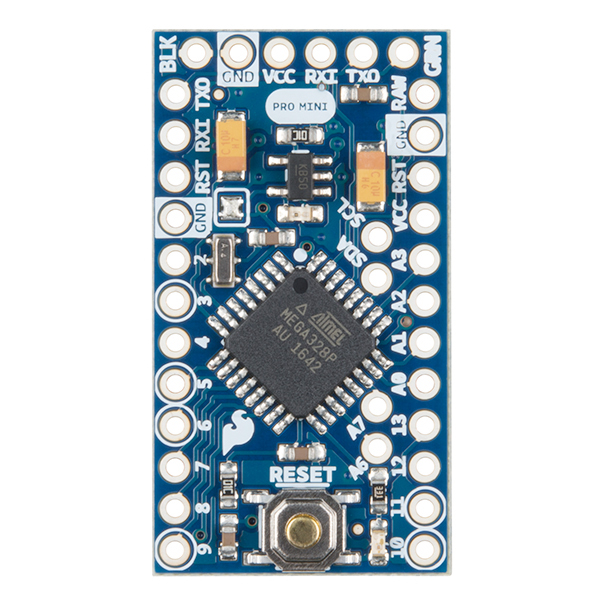
- 1 x Arduino Mini Pro
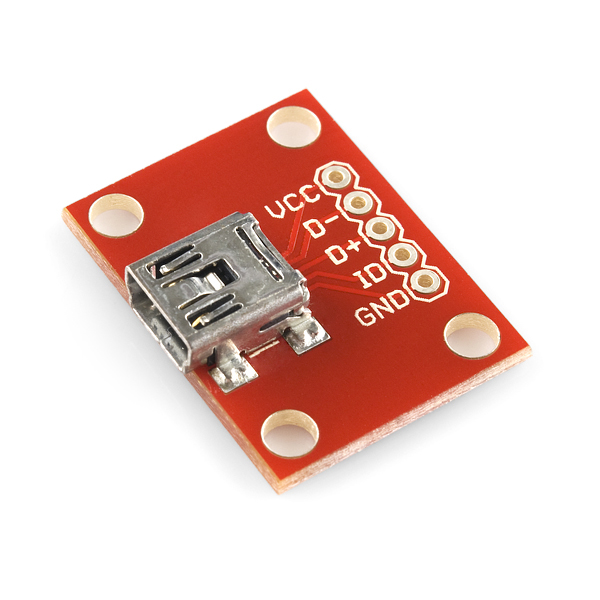
- 1 x Mini usb breakout
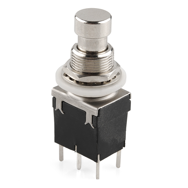
- 4 x Stomp Switches
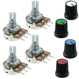
- 4 x Knob potentiometers
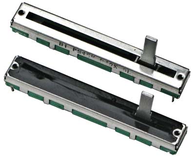
- 3 x Sliding potentiometers(Faders)
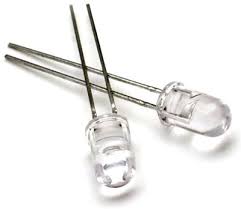
- 4 x LEDs
Description
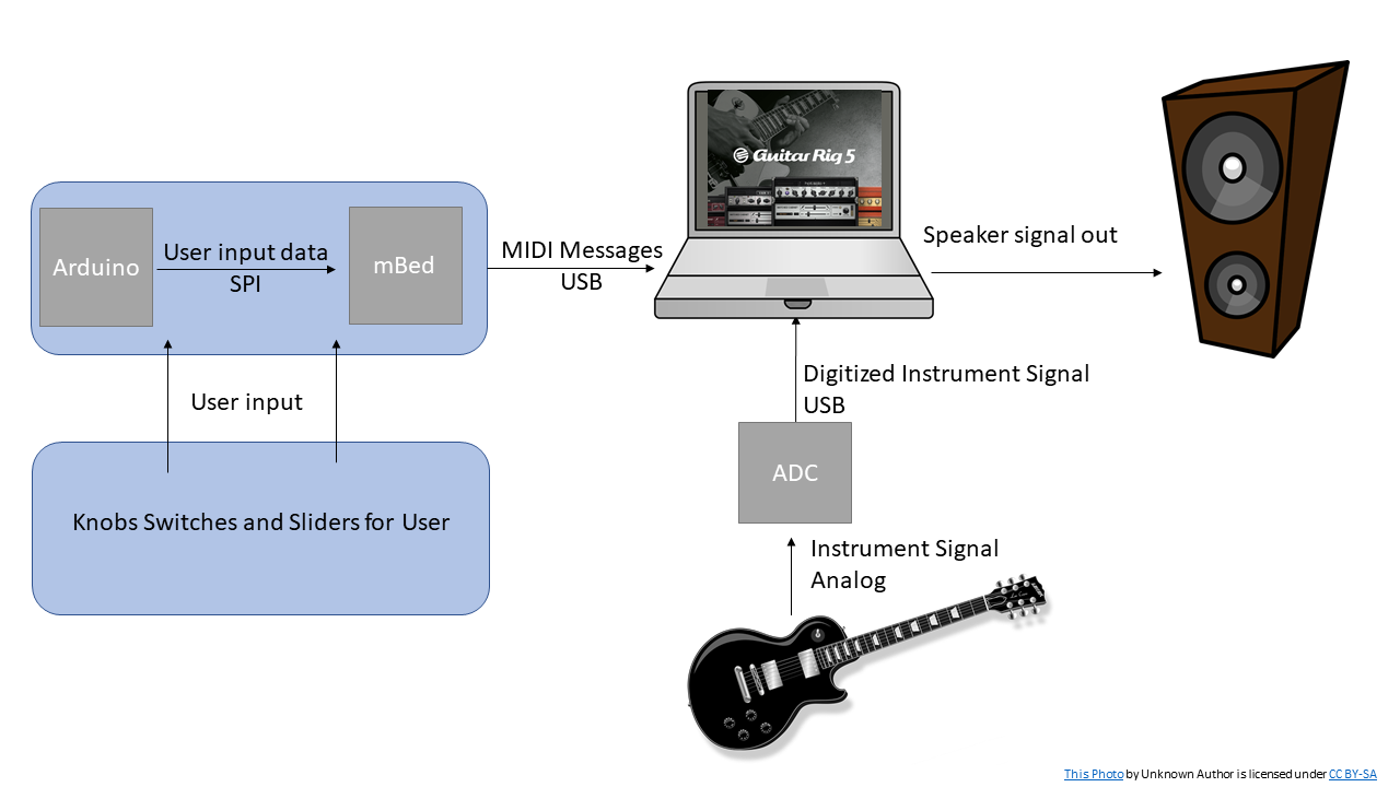
A MIDI foot controller designed for guitar players to use with amp and effects modeling software like Guitar Rig 5. The board will utilize the mbed and MIDIUSB library to interface with a computer running Guitar Rig 5. The user inputs will be expanded using an Arduino mini pro connected to the mbed through an SPI bus.
What is MIDI:
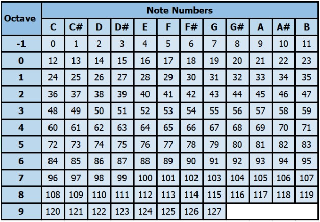
MIDI (Musical Instrument Digital Interface) is a serial communications standard designed for music applications. DAWs (Digital Audio Workstations) used to mix and master music tracks or amp modeling software for guitar players are designed to receive MIDI messages from controllers and interact with the application accordingly. An online MIDI keyboard is available at http://www.caseyrule.com/projects/piano/ and the HelloWorld for MIDIUSB is available at https://os.mbed.com/cookbook/USBMIDI. The hello world steps through notes 48 to 84 which is standardized to the notes in the table below. The standard for pre-programmed notes values and switches. Guitar Rig does not use the midi messages not to signify notes, but pairs these note commands to virtual knobs and switches in the application. More information on MIDI is available at at https://learn.sparkfun.com/tutorials/midi-tutorial/all.
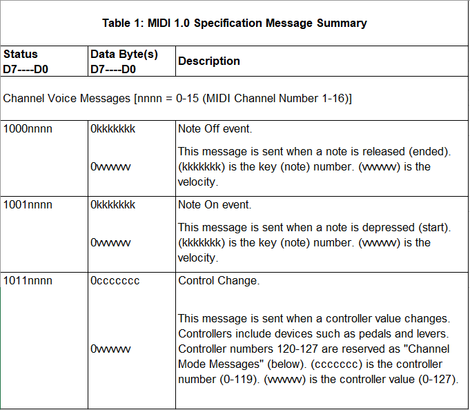
The standard message packet consist of a status bye and at at least one data byte. The three message types in this project are:
Setting Up the Project
Arduino Mini Pro
Most of the following info is for people who have little to no experience working with arduino. There are also details on setting up SPI on the arduino side.
You can download the arduino IDE from the following link https://www.arduino.cc/en/Main/OldSoftwareReleases.
The verify button on the Arduino IDE compiles your code and can be identified by the checkmark in the top right corner of the GUI. The upload button automatically puts your program onto the pro mini and can also be identified by an arrow pointing to the right. Just remember to reset the pro mini after uploading a new program.
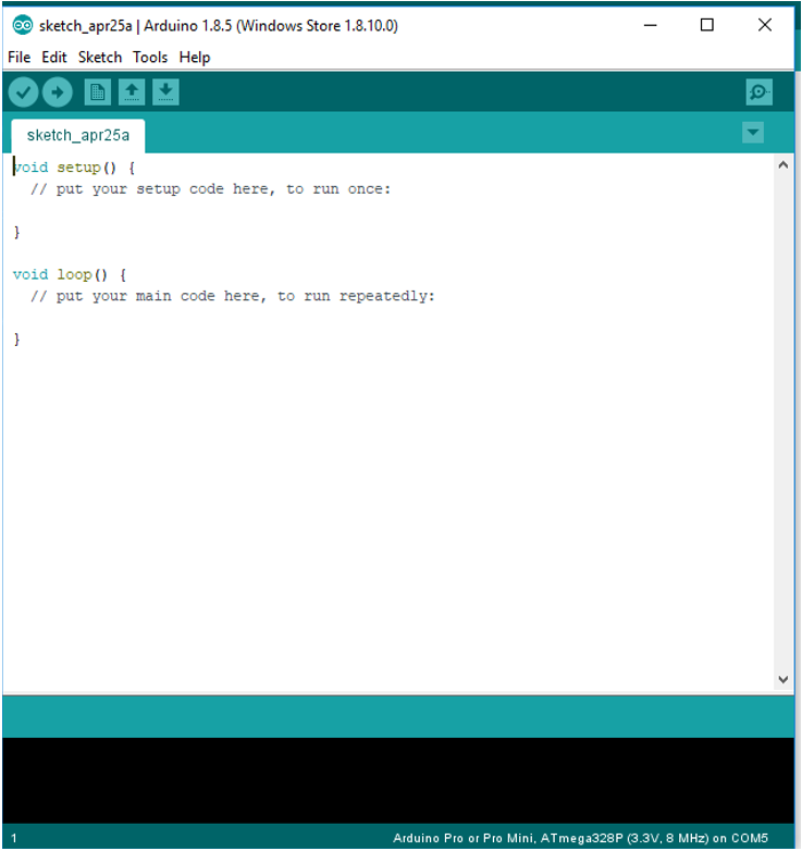
Arduino syntax is pseudo-C, so writing the code should be intuitive. If not, the Arduino APIs can be found online. For this project, the SPI master example code and API were very useful. Finding documentation for various Arduino APIs is similar to the mbed handbook. The void setup() function only runs once and is used to initialize variables and setup devices. The void loop() function is similar to while(1) on the mbed and is where your main loop runs.
You can test your mini pro by selecting a basic blinky program from drop down box shown in the image:

This https://www.arduino.cc/en/Tutorial/DigitalPotControl is a good example of how to setup the Arduino as a master. Another good resource: http://tronixstuff.com/2011/05/13/tutorial-arduino-and-the-spi-bus/.
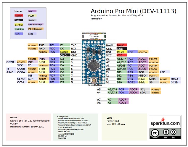
Arduino Pro Mini Pin Layout
Guitar Rig 5
Once you have the Arduino IDE set up, you can move on to Guitar Rig 5.
Download mbed code below:
The download is available at https://www.native-instruments.com/en/products/komplete/guitar/guitar-rig-5-pro/downloads/ step through the installer.
Check your devices in the preference. You most likely will need to install ASIO4ALL from http://www.asio4all.org/.
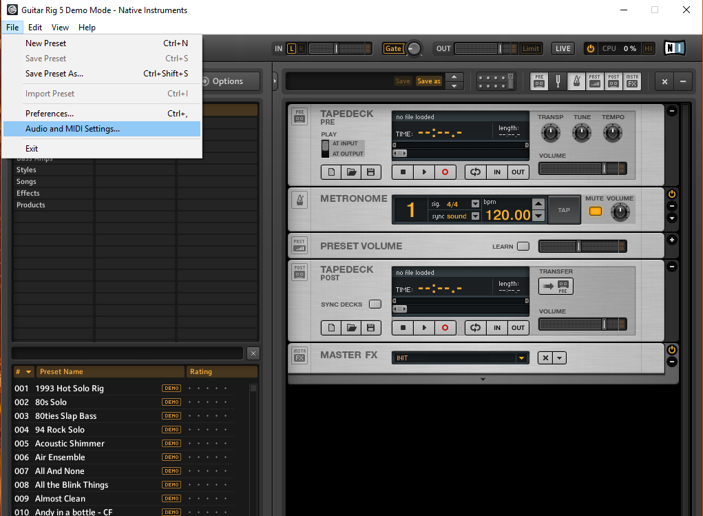
Once installed open Guitar Rig and go to file->Audio and MIDI Settings
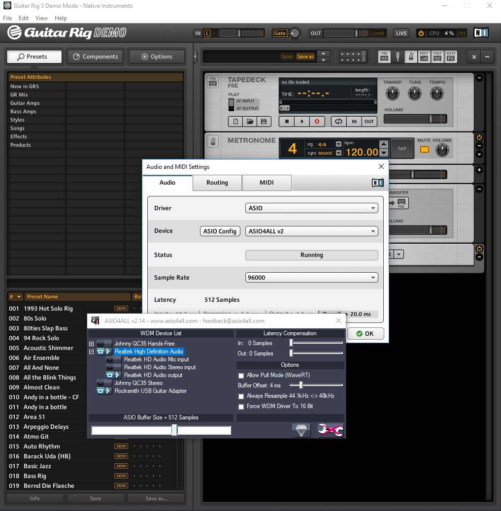
Click on the “ASIO Config” button and make sure only your input from instrument and output to the speaker are selected.
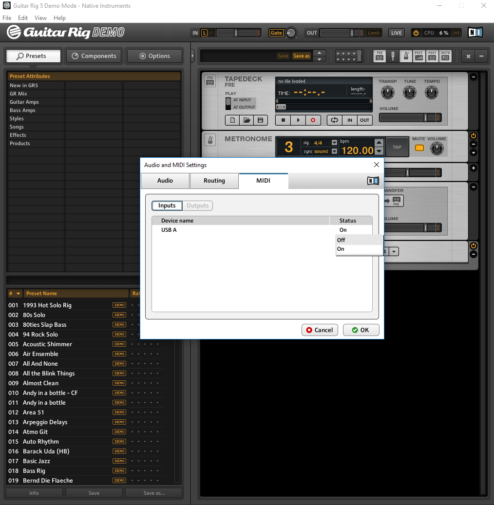
You'll then need to go to the MIDI tab and make sure that your new MIDI controller is turned on in Guitar Rig 5.
You should be able to rock on from here:
Implementation
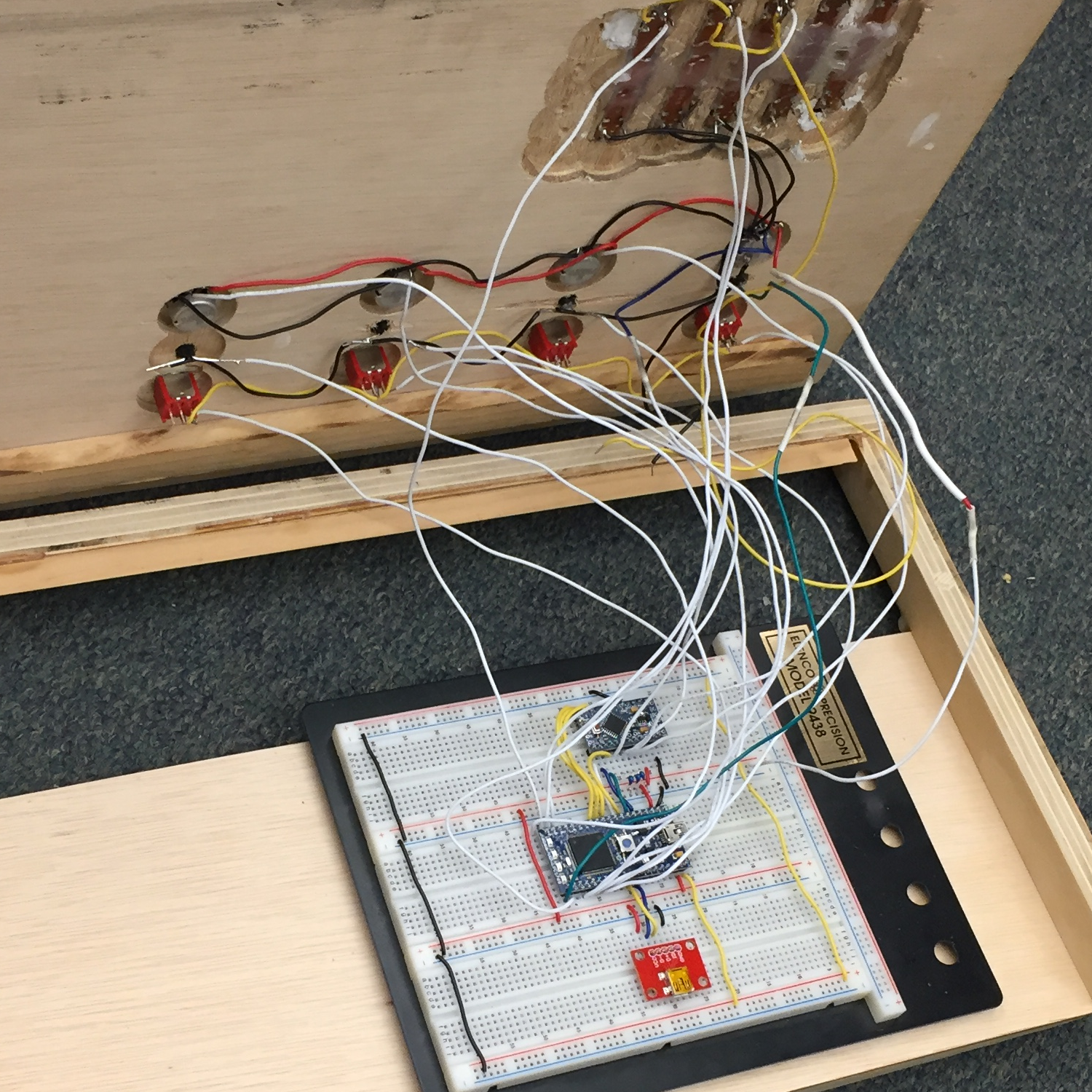
Values read from the potentiometers are transmitted to the mbed through an SPI Bus. A 3-bit bus is being used to determine which potentiometer is being changed. SPISlave class was used to configure the mbed as a slave. Luckily for us, there was a MIDI controller library for mbed already written. We used the library to send commands to the Guitar Rig 5 software from the mbed. The mini pro was used to take in the analog data from the potentiometers and push them to the mbed. The mbed does not have enough analog inputs for the number of potentiometers required, so the mini pro was a good option due to its extra analog input pins.
SPI
We used a serial peripheral interface bus to transfer the potentiometer data from the Arduino pro mini to the mbed. The pro mini was acting as the master and the mbed as the slave. We chose to do our implementation in this way because the mbed does not have enough analog inputs to support all of the analog devices we were trying to use. When attempting to implement a master-slave configuration like this, be sure to add a large enough delay after the data is transferred on the Arduino side. Not having enough delay will cause the data to be cut off too early resulting in incorrect readings from the potentiometer. To allow for the mbed to be configured as a slave, we used the SPI slave class. This is included in the mbed.h library.
Mbed's Hello World example (contains a link to the SPI Wikipedia page which is helpful):
https://os.mbed.com/handbook/SPI
Mbed Spi slave example:
https://docs.mbed.com/docs/mbed-os-api-reference/en/5.1/APIs/interfaces/digital/SPISlave/
Mbed Code
main.cpp
#include "mbed.h"
#include "USBMIDI.h"
#include "PinDetect.h"

#define SPI_CC_START_NUM 102
#define MBED_CC_START_NUM 20
#define MBED_SWITCH_START 70

USBMIDI midi;

//Serial pc(USBTX,USBRX);

SPISlave device(p5, p6, p7, p8);

BusIn pot_id_bus(p10, p11, p12);
int pot_id;

DigitalOut led1(p21);
DigitalOut led2(p22);
DigitalOut led3(p23);
DigitalOut led4(p24);

PinDetect  pinD1(p25);
PinDetect  pinD2(p26);
PinDetect  pinD3(p27);
PinDetect  pinD4(p28);

AnalogIn analog1(p20);
AnalogIn analog2(p19);
AnalogIn analog3(p18);

// foot switches
bool sw1 = 0;
bool sw2 = 0;
bool sw3 = 0;
bool sw4 = 0;


// continuous controlls
int cc1 = 0;
int cc2 = 0;
int cc3 = 0;
int last_cc1 = 0;
int last_cc2 = 0;
int last_cc3 = 0;

uint8_t v; // spi value read

uint32_t count = 0; // spi receive count for debug purposes

void key1Pressed( void )
{
    sw1 = !sw1;
    if(sw1)
        midi.write(MIDIMessage::NoteOn(MBED_SWITCH_START));
    else
        midi.write(MIDIMessage::NoteOff(MBED_SWITCH_START));
}
//
void key2Pressed( void )
{
    sw2 = !sw2;
    if(sw2)
        midi.write(MIDIMessage::NoteOn(MBED_SWITCH_START+1));
    else
        midi.write(MIDIMessage::NoteOff(MBED_SWITCH_START+1));
}

void key3Pressed( void )
{
    sw3 = !sw3;
    if(sw3)
        midi.write(MIDIMessage::NoteOn(MBED_SWITCH_START+2));
    else
        midi.write(MIDIMessage::NoteOff(MBED_SWITCH_START+2));
}

void key4Pressed( void )
{
    sw4 = !sw4;
    if(sw4)
        midi.write(MIDIMessage::NoteOn(MBED_SWITCH_START+3));
    else
        midi.write(MIDIMessage::NoteOff(MBED_SWITCH_START+3));
}

int main()
{
//    pc.printf("Hello World\n\r");

    // declare digital pins detects
    pinD1.mode(PullDown);
    pinD1.attach_asserted(&key1Pressed);
    pinD2.mode(PullDown);
    pinD2.attach_asserted(&key2Pressed);
    pinD3.mode(PullDown);
    pinD3.attach_asserted(&key3Pressed);
    pinD4.mode(PullDown);
    pinD4.attach_asserted(&key4Pressed);
    // digital pin detects frequencies
    pinD1.setSampleFrequency(); // Defaults to 20ms.
    pinD2.setSampleFrequency(); // Defaults to 20ms.
    pinD3.setSampleFrequency(); // Defaults to 20ms.
    pinD4.setSampleFrequency(); // Defaults to 20ms.

    device.format(8, 0); // 16 bits per message, SPI_MODE 0
    device.frequency(16e6);
    device.reply(0x01);         // Prime SPI with first reply
    device.reply(0x01);         // Prime SPI with first reply again

    while (1) {
        // set pedal led's
        led1 = sw1;
        led2 = sw2;
        led3 = sw3;
        led4 = sw4;

        // mbed cc's
        cc1 = (int)(127*analog1.read());
        cc2 = (int)(127*analog2.read());
        cc3 = (int)(127*analog3.read());

        if(cc1 != last_cc1) {
            last_cc1 = cc1;
//            pc.printf("cc1: %d\n\r",cc1);
            midi.write(MIDIMessage::ControlChange(MBED_CC_START_NUM+0,cc1));
        }
        if(cc2 != last_cc2) {
            last_cc2 = cc2;
//            pc.printf("cc2: %d\n\r",cc2);
            midi.write(MIDIMessage::ControlChange(MBED_CC_START_NUM+1,cc2));
        }
        if(cc3 != last_cc3) {
            last_cc3 = cc3;
//            pc.printf("cc3: %d\n\r",cc3);
            midi.write(MIDIMessage::ControlChange(MBED_CC_START_NUM+2,cc3));
        }
//
//
        while(device.receive()) {
            v = device.read();   // Read byte from master
            switch(pot_id_bus) {
                case 0x0:
                    pot_id = 0;
                    break;
                case 0x1:
                    pot_id = 1;
                    break;
                case 0x2:
                    pot_id = 2;
                    break;
                case 0x3:
                    pot_id = 3;
                    break;
                case 0x4:
                    pot_id = 4;
                    break;
            }
            //pc.printf("received value: %d\n\r", v);
//            pc.printf("id: %d\n\r",pot_id);
//            ++count;
//            pc.printf("count: %d\n\r", count);
            midi.write(MIDIMessage::ControlChange(SPI_CC_START_NUM+pot_id,v));
            device.reply((v + 1) % 0x100); // Make this the next reply
        }

        // wait to allow PinDetect to have some cpu time
        wait(.1);
    }
}
//}
Arduino Code
Arduino
#include <SPI.h>

#define NUM_POTS 4 // number of potentiometers being read from the arduino pro mini
#define MAP_SCALAR 1020 // max reading from pot, ideally this is 1024 on arduino but varies with pot quallity
#define DEL 180

SPISettings mySPISettings(16e6, MSBFIRST, SPI_MODE0); // (clock freq, MSBF/LSBF, SPI MODE)

const int ss = 10; // using digital pin 10 for SPI slave select

int potValue[NUM_POTS]; //Holds current analog control values
int last_potValue[NUM_POTS]; //Holds previous analog control values

unsigned int count;

byte pots[8]; //Stores pin names of analog channels

void setup()
{
//  Serial.begin(9600);      // open the serial port at 9600 bps:

  pinMode(ss, OUTPUT); // we use this for SS pin
  SPI.begin(); // wake up the SPI bus.

  pinMode(7, OUTPUT);
  pinMode(8, OUTPUT);
  pinMode(9, OUTPUT);

  pots[0] = A0;
  pots[1] = A1;
  pots[2] = A2;
  pots[3] = A3;
  pots[4] = A4;
  pots[5] = A5;
  pots[6] = A6;
  pots[7] = A7;
}

void loop()
{
  // for each pot
  for (int i = 0; i < NUM_POTS; ++i) {

    // read analog in and scale to 00-127]
    potValue[i] = analog2control(analogRead(pots[i]));

    // push data to mbed thru SPI
      if (potValue[i] != last_potValue[i]){
      spi_push_value(i, (unsigned int)potValue[i]);
      last_potValue[i] = potValue[i];
    }
  }
}


void spi_push_value(int id, unsigned int value)
{
  switch (id) {
    case 0:
      digitalWrite(7, LOW);
      digitalWrite(8, LOW);
      digitalWrite(9, LOW);
      break;
    case 1:
      digitalWrite(7, HIGH);
      digitalWrite(8, LOW);
      digitalWrite(9, LOW);
      break;
    case 2:
      digitalWrite(7, LOW);
      digitalWrite(8, HIGH);
      digitalWrite(9, LOW);
      break;
    case 3:
      digitalWrite(7, HIGH);
      digitalWrite(8, HIGH);
      digitalWrite(9, LOW);
      break;
      break;
    case 4:
      digitalWrite(7, LOW);
      digitalWrite(8, LOW);
      digitalWrite(9, HIGH);
      break;
  }
  SPI.beginTransaction(mySPISettings);
  digitalWrite(ss, LOW);
  SPI.transfer(value);
  digitalWrite(ss, HIGH);
  SPI.endTransaction();
  delay(DEL);
}

int analog2control(int in_value)
{
  if (in_value > MAP_SCALAR)
    return 127;
  else
    return (int) (in_value * (127.0 / MAP_SCALAR));
}
Wiring
| Arduino Mini Pro | Mbed |
|---|---|
| VCC | VU |
| gnd | gnd |
| p11 | p5 |
| p12 | p6 |
| p13 | p7 |
| p10 | p8 |
| p7 | p10 |
| p8 | p11 |
| p9 | p12 |
| Mbed | Mini Usb Breakout |
|---|---|
| VU | VCC |
| gnd | gnd |
| D- | D- |
| D+ | D+ |
Schematic and Block Diagram

Future Improvements
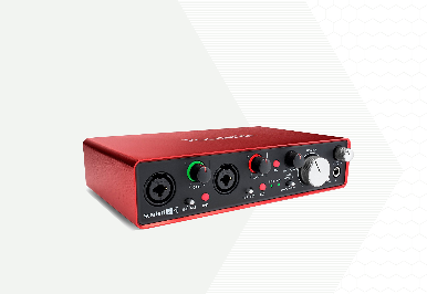
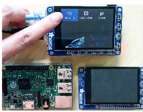
Some improvements that could be made to the project are converting the entire system into a single windows IoT device, adding an onboard LCD screen that would display information about what is going on in whatever software is being used, and adding a home studio sound processing card. Converting the MIDI controller to an IoT device would make the whole system more compact by eliminating the need for a laptop and a speaker. The LCD would be a part of the interface for the IoT device. It would display information about what software function each analog device controls. The sound processing card would be implemented to improve overall sound quality of the MIDI controller.
Please log in to post comments.
