xbee communication
Page last updated
17 Apr 2012, by
 Harris Junaid
.
7
replies
7 comments on xbee communication:
harrisjunaid
#
27 Mar 2012

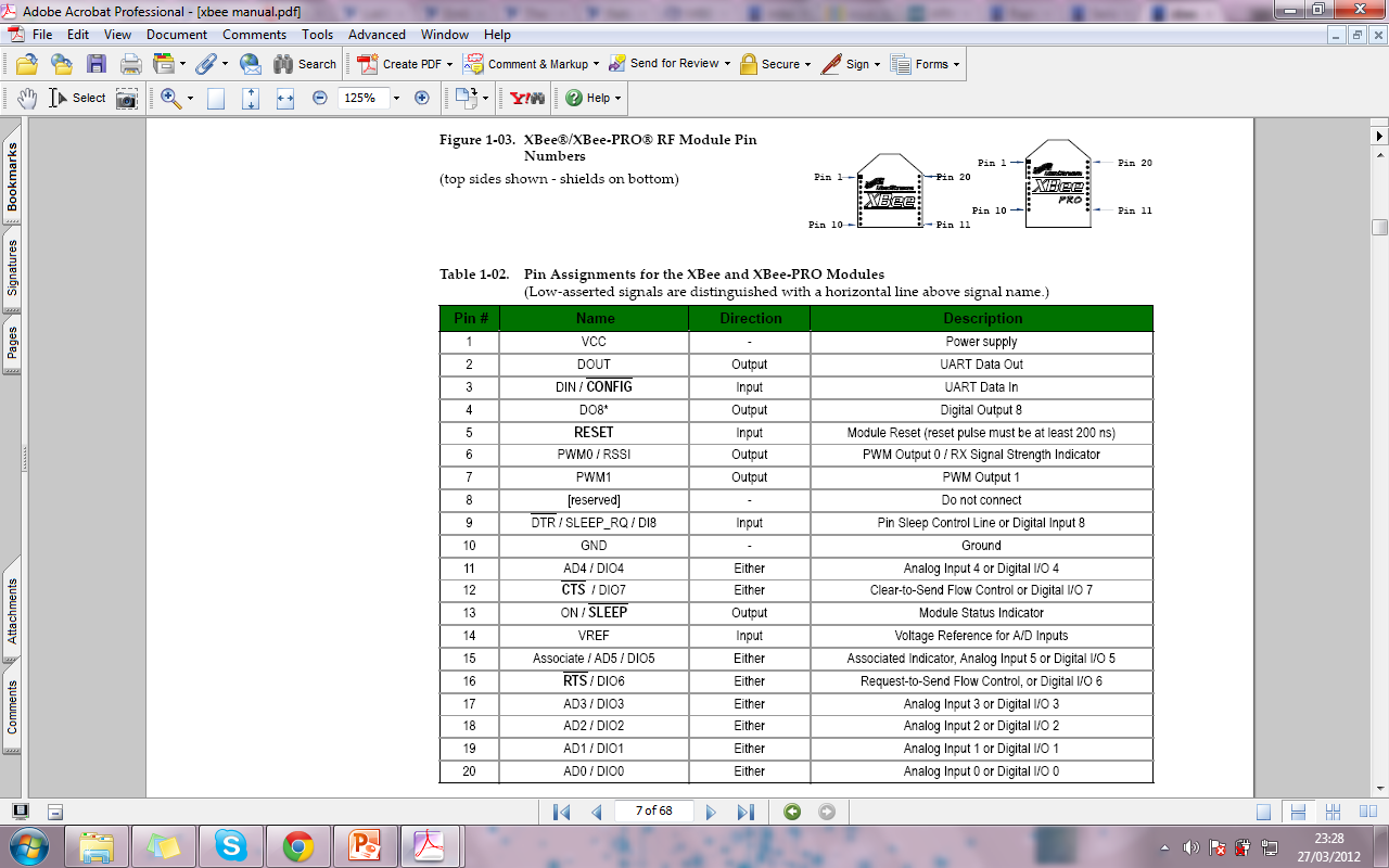
Notes:
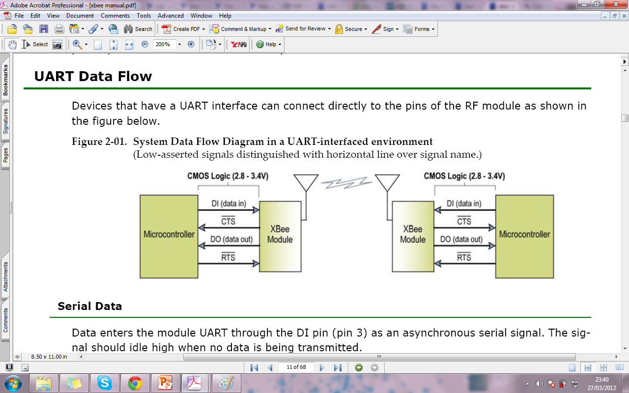
- • Minimum connections: VCC, GND, DOUT & DIN
- • Minimum connections for updating firmware: VCC, GND, DIN, DOUT, RTS & DTR
- • Signal Direction is specified with respect to the module
- • Module includes a 50k pull-up resistor attached to RESET
- • Several of the input pull-ups can be configured using the PR command
- • Unused pins should be left disconnected
harrisjunaid
#
27 Mar 2012
harrisjunaid
#
27 Mar 2012
Associate
LED pin (pin 15) and the commissioning button pin (pin 20). The Associate LED will flash differently
depending on the state of the module, and a pushbutton attached to pin 20 can enable
various deployment and troubleshooting functions without having to send UART commands.
If analog sampling is desired, VRef (pin 14) should be attached to a voltage reference.
harrisjunaid
#
27 Mar 2012

xbee---mbed
- 1 VCC to 3.3v
- 2 DOUT to mbed serial rx (e.g. p10)
- 3 DIN to mbed serial tx (e.g. p9)
- 4 not connected
- 5 RESET to mbed digital out (e.g p11)
- 6-9 not connected
- 10 GND to 0v/GND
- 11-20 not connected
harrisjunaid
#
27 Mar 2012
harrisjunaid
#
28 Mar 2012
harrisjunaid
#
28 Mar 2012
Please log in to post comments.
Notes: