Mbed WiFi Alarm System
Description
An ESP8266 WiFi chip is used to connect the Mbed LPC1768 to WiFi. Once a connection is made, the user accesses the given web page that displays the statuses of the Alarm System. Note that this is a static webpage; any changes made on the Mbed will only correlate on the webpage once the webpage has been refreshed. The background of the webpage mirrors the status of the alarm; green if the alarm is off, red when the alarm is sounding. A push button represents an “open door”. Once the door is opened, a timer starts. The status of both the door and the timer are also reflected on the webpage. Once the time runs out, the alarm sounds. The user will see the screen on the webpage turn red. Once the user punches in the correct secret code, the alarm will be disabled and the webpage will turn green again.
Demo Video
Import programIoTAlarmSystem
IoT Alarm System with pushbutton for door, webpage for viewing status, and keypad for disabling alarm.
Hookup Guide:
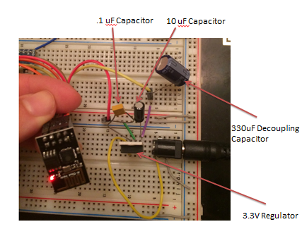
WiFi Chip with External 3.3V power: The ESP8266 WiFi chip is used in this scenario. The chip needs an external 3.3V; using the voltage from the Mbed doesn’t leave enough to power any other devices. Using the breadboard adapter for the 5V 2A AC adapter barrel jack and a 3.3V voltage regulator, LM2937, the external 3.3V power can be supplied to the chip. The regulator needs a .1uF decoupling capacitor on the unregulated pin and 10uF capacitor on the regulated pin.

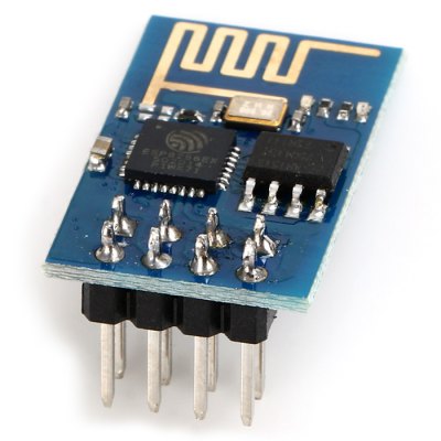
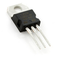
The following diagrams illustrate the pin out for the chip. Don’t forget the 330uF decoupling capacitor across the power.
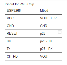
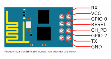
Detailed Picture of WiFi Chip to Power Hookup
For more information on wifi chip: https://developer.mbed.org/users/4180_1/notebook/using-the-esp8266-with-the-mbed-lpc1768/
Touch Keypad: Freescale MPR121 using I2C Interface The touch keypad is used to input the code to stop the alarm from sounding. Follow the pinout as shown in the table below. A 4.7K ohm pull up resistor must be used for the SDA and SCL pins.
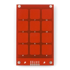
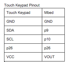
For more information on keypad: https://developer.mbed.org/components/MPR121-I2C-Capacitive-Touch-Keypad/
Pushbutton: The push button signifies an “open door”; when pressed, it triggers the alarm. Follow the pin out table as shown below. A pull up resistor must be implemented in order for the push button to work. Alternatively, an internal pull-up resistor can be used by calling pin.mode(PullUp); on a DigitalIn pin.


For more on pushbuttons: https://developer.mbed.org/users/4180_1/notebook/pushbuttons/
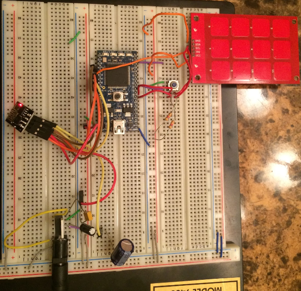
Hookup Image
Ideas for Improvements
- Writing socket code for the webpage so it is no longer static and reflects the status of the alarm system in real time
- Figuring out how to include rtos.h so threads can be run and interesting features such as a speaker that sounds an actual alarm can be implemented
- Having a button to disable the alarm from the webpage
Please log in to post comments.
