LIDAR 2-D Mapping
Overview
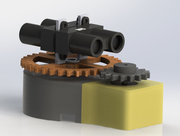
This wikipage is designed to give users an understanding of how to create a basic 2d mapping system using a LIDAR Lite v2 sensor, an mbed and stepper motor. The LIDAR used can detect distances of up to 40 meters. The stepper motor is used to rotate the LIDAR 360°. The mbed is used to retrieve range finding data from the LIDAR and send the data to be processed by a GUI on a windows computer. A 3D printed frame was used to house the whole system.

Parts List
Lidar Lite v2
Lidar, or LIght Detecting and Ranging, is a distance detecting sensor. Lidar works by emitting a laser pusle at a traget and analyzing the time it takes for the beam to reflect and return to its source. You can read more about how lidar works at this link. The Lidar in our system is the Lidar Lite v2. You can find its specification and where to purchase from at the products homepage. This project will utilize Lidar to gather information about the dimension of the map. You can learn all about the wiring, the library we used, and how the lidar lite v2 works at the mbed component page
Stepper Motor
The stepper motor component of this project is used to both move the lidar and calculate the angle from 0-360 degrees that the lidar is pointing at in the 2-D plane of our map. Stepper motors are designed to move a step each time a step signal is received. Each "step" is a predetermined circular degree movement of the electro-mechanical motor. You can read more about how stepper motors work at this link. The particular stepper motor utilized for this project is the sparkfun ROB-09238 with 0.9 degree stepping angle.
Stepper Motor Driver
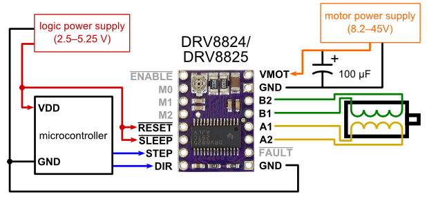
Stepper motors need to be driven with a stepper motor driver. This a a specialized dual H-bridge circuit that acts as a relay for providing the stepper motor with the high power it needs as well as providing the correct signals to allow the stepper motor to move a step. The stepper motor driver utilized for this project is the DRV8825 from Texas instruments which can be purchased from Pololu. Provided below is the data sheet for the driver.
Slip Ring
A slip ring is an electromechanical device that allows the transmission of power and electrical signals from a stationary to a rotating structure. This allows for the LIDAR to spin freely without tangling the wires connected to the mbed. You can read more about slip rings and how they work at this Wikipedia page. Also below are links for purchasing the slip used for this project.
Frame and Assembly
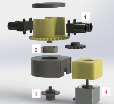
The frame was designed in Solidworks and 3D printed with ABS or laser cut from wood .The picture below illustrates the interconnection of the components and how they were assembled. Below is also the parts created in Solidworks.


1. Lidar Lite v2
2. Bearing
3. Slip Ring
4. Stepper Motor
Wiring
| mbed | Lidar-lite |
|---|---|
| 5V=VU | 5V |
| SDA=P28 | SDA |
| SCL=P27 | SCL |
| Gnd | GND |
| mbed | DRV8825 | Stepper Motor | Power Supply |
|---|---|---|---|
| VMOT | + | ||
| GND top | - | ||
| DigitalOut =P21 | EN | ||
| DigitalOut = p22 | M0 | ||
| DigitalOut = p23 | M1 | ||
| DigitalOut = p24 | M2 | ||
| Gnd | RST | ||
| Gnd | SLP | ||
| DigitalOut =P25 | DIR | ||
| PwmOut =P26 | STEP | ||
| Gnd | GND bottom | ||
| B2 | BLUE | ||
| B1 | YELLOW | ||
| A1 | RED | ||
| A2 | GREEN |

- Schematic showing the connections to the stepper motor.
Code
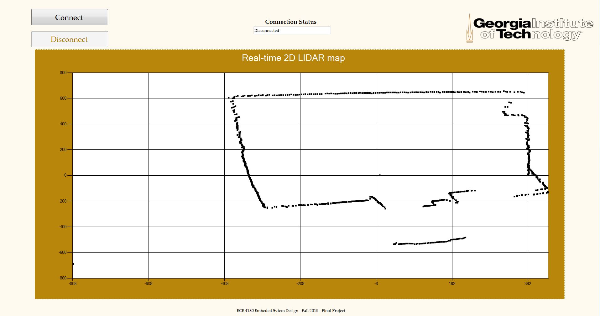
The project consists of two separate codes. One is for the mbed and the other is for the windows computer. The code for the mbed deals with all the hardware to allow the lidar to move and scan the the environment. The code for windows is written in C#. It takes in serial data from the mbed, in the form of and x and y coordinates, and plots them in real time to generate a map. The C# GUI also turns on and off the lidar system.
C# GUI
Download the C# library used to create the LIDAR GUI below. The COM port will have to be correctly set by clicking on the serial port button in visual studio and changing the COM port property. It's currently set to COM125.
Picture of GUI

Mbed Code
Below are the libraries for both the DRV88255 Stepper Motor Driver, Lidar litev2 driver, and MODSERI respectively:
Fully functional driver for the DRV88255 stepper motor driver. Includes microstepping, speed, disable and enable. LidarLitev2 Library for distance reading. Capable of both single distance reads and continuous distance read setup. Bug fix releaseImport libraryDRV88255
Import libraryLidarLitev2
Import libraryMODSERIAL
Below is the code used in conjunction with the libraries and C# GUI to make the system work://
Lidar_2D_Mapping.cpp
#include "LidarLitev2.h"
#include "DRV8825.h"
#include "MODSERIAL.h"
#include "math.h"

#define PI 3.14159265359

Serial pc(USBTX, USBRX);

DRV8825 stpr_mtr(p21, p22, p23, p24, p25, p26);
DigitalIn pinMode(p19);

LidarLitev2 Lidar(p28, p27);


int main()
{
    stpr_mtr.direction = 1;
    pc.baud(230400);
    Lidar.configure();
    float degree = 0, x, y;
    int distance;
    char e;
    while(1){
         if(pc.readable()) {
             e = pc.getc();
        }
        while (e == 'e'){
            distance = Lidar.distance();
            x = distance*cos(degree*(PI/180));
            y =  distance*sin(degree*(PI/180));
            stpr_mtr.settings(1, 0, 400);
            degree += .45;
            if(degree >= 360) degree = 0;
            pc.printf("%4.0f,%4.0f\n", x, y);
          if(pc.readable()) {
             e = pc.getc();
            }
          if (e == 's') break;
        }
    }
}
Import programLidar_2D_Mapping
Software for mapping with the Lidar lite v2, stepper motor, and stepper motor driver
Live Demo
The following demo uses a GUI written in C# to draw a 2-D map and based on data read from the LIDAR and stepper motor.
Please log in to post comments.


