Audio channel divider and compensator.
Dependencies: DokuFFTPACK DokuUSBDevice DokuUSBHost DokuUSBHostWithIso mbed
Fork of Peach_AudioChannelDividerAndCompensator by
日本語の説明は後半にあります。
Outline
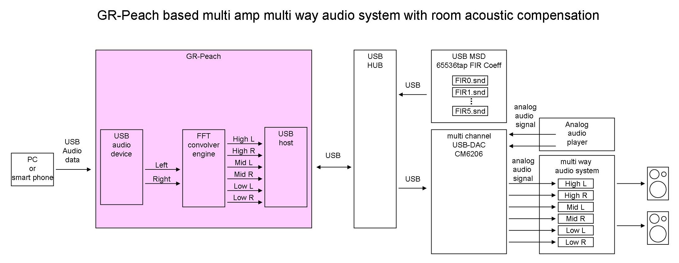
This is audio channel dividing filter for multi-way multi-amplifier systems with compensation for system and room response. This program uses 32768 taps of real time 6ch floating point FIR (by FFT and superimpose) for accurate compensation of low frequency. Either USB digital audio stream (USB1) or analog audio signal (LINE-IN of USB-DAC) can be accepted. GR-Peach divide up them into six channel (Low,Mid,High each L,R). Then outputs them to the multi-channel USB-DAC as a USB host (USB0). 32767 taps of FIR coefficient is given by the files in the USB MSD (USB0).
GR-Peach's superabundant process power solves real time 6ch/32kTaps floating point audio FIR in textbook method without any optimization.
Sorry
This cord works but doesn't tested completely, can work with multi-channnel USB-DAC CM6206 chip inside.
Connection
To use this program, connect USB0 of GR-Peach to a self powered USBHUB, a multi-channel USB-DAC(CM6206 chip inside / e.c.DN-USBSA6CHOPThttp://www.donya.jp/site/item/item_20087.html or RA-AUD51) and a USB mass storage device (coefficient files are saved) to the USBHUB as shown above.
If you would like to accept digital audio stream (16bit/48ksps) as a USB audio device, connect USB1 of GR-Peach to the PC. If not, analog stereo audio signal is accepted.
Filter setting
You can get your favorite cross-over and compensation characteristics modifying FIR coefficient files named Fir_Ch0.snd to Fir_Ch5.snd. Coefficient files are signed 16 bit integer raw formatted sound file (without any header) having time domain responses of the FIRs. Coefficient file have 65536 samples of filter response. but second-half portion of the file (32768 samples) must be zero to work superimpose correctly. If you want minimum phase FIR, filter impulse will be placed at the first sample of the file. If you want liner phase FIR, filter impulse will be placed at 16384 sample of the file.
Sample coefficient files
Sample coefficient files are shown below. store below files in Root folder of USB mass storage device before running the program. These are files for two way systems. Since flatness of frequency response is archived by the compensation, full range speaker works very well without tweeter. In below files, ch0 and ch1 for full range speakers, ch2 and ch3 for low range speakers (woofers), ch4 and ch5 are not used. Of cause, system compensation coefficient is differ according to speaker unit, speaker enclosure, room, and amplifier. Below samples are for my speakers and room.
Compensated coefficient file with channel divider
ch0:full range(high):left:/media/uploads/dokunewon/fir_ch0.snd
ch1:full range(high):right:/media/uploads/dokunewon/fir_ch1.snd
ch2:woofer(mid):left:/media/uploads/dokunewon/fir_ch2.snd
ch3:woofer(mid):right:/media/uploads/dokunewon/fir_ch3.snd
ch4:not_used(low):left:/media/uploads/dokunewon/fir_ch4.snd
ch4:not_used(low):right:/media/uploads/dokunewon/fir_ch5.snd
channel divider without compensation (pushing the user button on the GR-Peach, below coefficients are used)
ch0:full range(high):left:/media/uploads/dokunewon/fir_ch0nc.snd
ch1:full range(high):right:/media/uploads/dokunewon/fir_ch1nc.snd
ch2:woofer(mid):left:/media/uploads/dokunewon/fir_ch2nc.snd
ch3:woofer(mid):right:/media/uploads/dokunewon/fir_ch3nc.snd
ch4:not_used(low):left:/media/uploads/dokunewon/fir_ch4nc.snd
ch4:not_used(low):right:/media/uploads/dokunewon/fir_ch5nc.snd
Filter bypass test coefficient
/media/uploads/dokunewon/fir_bypass.snd
Gain of each Filter
/media/uploads/dokunewon/gains.txt
Measuring system and generating filter coefficient
These coefficient files are generated by a home made audio analyzer tool works on PC below.
/media/uploads/dokunewon/inversex90.zip
Latest beta release /media/uploads/dokunewon/inversex72.zip (Smallest number shows the latest one)
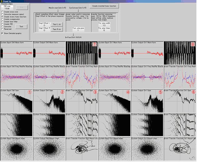
Use above tool reading below manual.
/media/uploads/dokunewon/inversex84.pdf
Latest beta release /media/uploads/dokunewon/inversex72.pdf (Smallest number shows the latest one)
Using this tool, you can configure cross-over frequency and filter dimension for two or three way multi-way multi-amplifier system, measure response of your room and system, generate inverse response transfer function using unique and refined algorithm to create compensation FIR coefficient.
Improvement in frequency characteristic by compensation
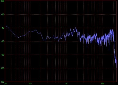
Average spectrum of white noise before compensation (By 2 way system High:F77G98-6 x 1 Low:F77G98-6 x 8)
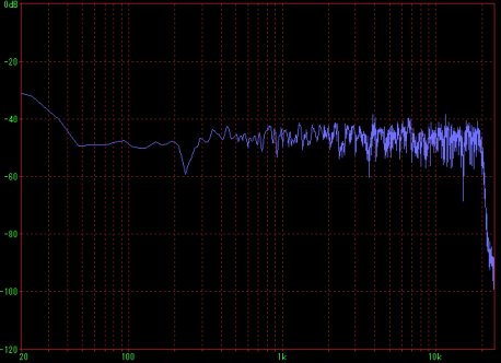
Average spectrum of white noise after compensation (By 2 way system High:F77G98-6 x 1 Low:F77G98-6 x 8)
Compensation example
Sorry. Some car noise from the road fronting my house recorded together.
Recorded playback sound by 2 way system (High:F77G98-6 x 1 Low:F77G98-6 x 8)
Early part : normal playback / latter part : compensated playback.
/media/uploads/dokunewon/samplef77g98-6.mp3
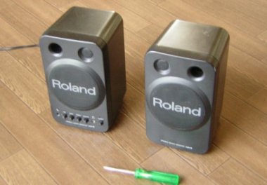
Recorded playback sound by low-cost powered small speaker Roland MA-8 (channel divider is not used)
Early part : normal playback / latter part : compensated playback.
/media/uploads/dokunewon/playbacksample.mp3
概要
システムの特性補償を行なうマルチアンプマルチウェイシステム用のオーディオチャンネルデバイダです。低音を正確に補正するために、32768タップのFIRを使用しています。GR-Peachの有り余る処理力で、教科書通りのフィルタアルゴリズムが(最適化なしで!)リアルタイムにオーディオ信号を処理します。
本ソフトはUSB1端子に入力されたデジタルステレオ音声信号(48kサンプル16ビットの)か、USB-DACのLINE-IN端子に入力されたアナログステレオ音声信号を、システム特性を補償すると同時に左右各3チャンネルに帯域分割して、マルチチャンネルUSB-DACに出力します。
おわび
このプログラムは一応動くのですが完全にテストされていません。USB-DACは内部にCM6206を使用したものだけに対応しています。

接続
上の図のように、USB0には(できればセルフパワーの)USBHUBを接続し、HUBには、マルチチャンネルUSBDAC(CM6206を使用した、DN-USBSA6CHOPThttp://www.donya.jp/site/item/item_20087.html あるいは RA-AUD51)とFIR特性ファイルを記録したUSBメモリを接続します。
デジタルオーディオ信号を入力する場合は、USB1端子にPC等を接続します。USB1端子に何も繋がなければ、USB-DACのLINE-IN端子のアナログオーディオ信号が入力されます。
フィルタの設定
FIR特性ファイル(Fir_Ch0.snd ~ Fir_Ch5.snd)を変更することで、好みの補正やクロスオーバー特性を得ることができます。特性ファイルはFIRの時間領域の応答を記録した16ビット符号付整数形式のヘッダなしモノラルRAW波形データです。特性ファイルには65536サンプルのフィルタ応答が記録されていますが、後ろ半分は重畳処理の都合でゼロとします。
見本の特性ファイル
見本の特性ファイルを次に示します。これらは、2ウェイシステム用のファイルです。これらのファイルはUSBMSDのルートフォルダに配置します。システム特性の補正によってフラットな周波数特性が実現されるので、トゥイータ無しのフルレンジスピーカーでも良い結果が得られます。チャンネル0と1がフルレンジ、2と3がウーファ、4と5は今回使用しません。もちろんシステムの補償はユニット、エンクロジャー、部屋、アンプ等によって変化します。下の例は、私のスピーカーと部屋のためのものです。(フルレンジは、F77G98-6左右各1本、ウーファはF77G98-6左右各8本を使用しています)
チャンネルデバイダの特性(補償付き)
ch0:full range(high):left:/media/uploads/dokunewon/fir_ch0.snd
ch1:full range(high):right:/media/uploads/dokunewon/fir_ch1.snd
ch2:woofer(mid):left:/media/uploads/dokunewon/fir_ch2.snd
ch3:woofer(mid):right:/media/uploads/dokunewon/fir_ch3.snd
ch4:not_used(low):left:/media/uploads/dokunewon/fir_ch4.snd
ch4:not_used(low):right:/media/uploads/dokunewon/fir_ch5.snd
チャンネルデバイダの特性(補償なし:ピーチの押しボタンを押すと、こちらの特性に切り替わります)
ch0:full range(high):left:/media/uploads/dokunewon/fir_ch0nc.snd
ch1:full range(high):right:/media/uploads/dokunewon/fir_ch1nc.snd
ch2:woofer(mid):left:/media/uploads/dokunewon/fir_ch2nc.snd
ch3:woofer(mid):right:/media/uploads/dokunewon/fir_ch3nc.snd
ch4:not_used(low):left:/media/uploads/dokunewon/fir_ch4nc.snd
ch4:not_used(low):right:/media/uploads/dokunewon/fir_ch5nc.snd
テスト用のバイパスフィルタ
/media/uploads/dokunewon/fir_bypass.snd
各フィルタのゲイン
/media/uploads/dokunewon/gains.txt
システムの測定とフィルタ特性の生成
上記の特性ファイルは次の自作のPC用測定分析ツールで生成しています。
/media/uploads/dokunewon/inversex90.zip
最新のベータ版 /media/uploads/dokunewon/inversex72.zip (数字が小さい方が最新です)

使い方は次のファイルを参照してください。
/media/uploads/dokunewon/inversex84.pdf
最新のベータ版 /media/uploads/dokunewon/inversex72.pdf (数字が小さい方が最新です)
このツールを使用して、クロスオーバーの周波数や次数、システム特性の測定、補償用の逆フィルタの生成が可能です。
補償による周波数特性の改善
補償前のホワイトノイズの平均スペクトラム (By 2 way system High:F77G98-6 x 1 Low:F77G98-6 x 8)

補償後のホワイトノイズの平均スペクトラム (By 2 way system High:F77G98-6 x 1 Low:F77G98-6 x 8)

補償による音声の変化
国道を通る自動車の音なども一緒に入ってますが、悪しからず。
2ウェイマルチアンプシステム (High:F77G98-6 x 1 Low:mid:F77G98-6 x 8)
前半:通常再生音/後半:補償再生音
/media/uploads/dokunewon/samplef77g98-6.mp3
低価格小型パワードスピーカー Roland MA-8
前半:通常再生音/後半:補償再生音
/media/uploads/dokunewon/playbacksample.mp3

filter.cpp
- Committer:
- dokunewon
- Date:
- 2015-10-19
- Revision:
- 12:d12709edf53d
- Parent:
- 6:3a337a5e5aa7
File content as of revision 12:d12709edf53d:
/*
 *  this is free software; you can redistribute it and/or modify
 *  it under the terms of the GNU General Public License as published by
 *  the Free Software Foundation; either version 2 of the License, or
 *  (at your option) any later version.
 *
 *  this software is distributed in the hope that it will be useful,
 *  but WITHOUT ANY WARRANTY; without even the implied warranty of
 *  MERCHANTABILITY or FITNESS FOR A PARTICULAR PURPOSE.  See the
 *  GNU General Public License for more details.
 *
 *  You should have received a copy of the GNU General Public License
 *  along with libfftpack; if not, write to the Free Software
 *  Foundation, Inc., 51 Franklin St, Fifth Floor, Boston, MA  02110-1301  USA
 */

#include <stdio.h>
#include "mytype.h"
#include "fftpack.h"
#include <math.h>
#include "mbed.h"
#include "USBHostMSD.h"

#define N 32768
#define N2 (N * 2)

extern DigitalOut myledR;

//frequency domain FIR coeffecient
//with compensation
//フィルタ係数(周波数領域)補正あり
FLOAT FilterL0[N2];
FLOAT FilterL1[N2];
FLOAT FilterL2[N2];
FLOAT FilterR0[N2];
FLOAT FilterR1[N2];
FLOAT FilterR2[N2];
//frequency domain FIR coeffecient
//without compensation
//フィルタ係数(周波数領域)補正なし
FLOAT FilterL0NC[N2];
FLOAT FilterL1NC[N2];
FLOAT FilterL2NC[N2];
FLOAT FilterR0NC[N2];
FLOAT FilterR1NC[N2];
FLOAT FilterR2NC[N2];
//frequency domain FIR coeffecient
//bypass (path through)
//フィルタ係数(周波数領域)バイパス(素通り)
FLOAT FilterBypass[N2];

//ゲイン
FLOAT ChannelGains[16];

//Buffer for wav format FIR coeffencent
//Wav形式のフィルタ形式読み込みバッファ
int16_t wav[N2];

//wave input buffer
//波形入力バッファ
int16_t Wav2Ch[N * 2];

//superimpose buffer (32k samples x 6ch)
//32kサンプル、6チャンネル、2回分の出力重畳用バッファ
int16_t Sip6Ch[N * 6 * 2];

//work buffer for FFT
//FFTワークエリア
FLOAT FftWork[2*N2+15];

//buffer for FFT source and destination
//FFT入出力バッファ
FLOAT FftIn[N2];
FLOAT fftOut[N2];

//multiplies complex number in array
//複素数の配列を掛け合わせる
void MulAry(FLOAT *m,FLOAT *f,FLOAT *in)
{
    int i;
    m[0]=in[0]*f[0];
    for(i = 1;i < N2-2;i+=2)
    {
        m[i]=in[i]*f[i]-in[i+1]*f[i+1];
        m[i+1]=in[i]*f[i+1]+in[i+1]*f[i];
    }
    m[N2-1]=in[N2-1]*f[N2-1];
}

//applies FIR filter
//フィルタ処理を行なう
int Fir(int16_t *out, FLOAT *f, FLOAT *in)
{
    int ovf = 0;
    int i;

    //周波数領域でfとinを乗算してフィルタを畳み込み、fftoutに入れる
    MulAry(fftOut,f,in);
    //畳込み結果(fftout)を逆実DFTして、フィルタ出力波形を求めfftoutに入れる
    rfftb(N2, fftOut, FftWork);
    //
    //  フィルタ結果を出力バッファに重畳する
    //
    //出力バッファにフィルタ出力を重畳する
    for (i = 0;i < N2; i++)
    {
        FLOAT ftmp = (FLOAT)out[i*6] + fftOut[i];
        //オーバーフローしたらクリップさせる。
        if(ftmp > 32700.0)
        {
            out[i*6] = 32700;
            ovf++;
        }
        else if(ftmp < -32700)
        {
            out[i*6] = -32700;
            ovf++;
        }
        //出力(重畳)バッファに結果を足し込む
        else
        {
            out[i*6] += (int16_t)fftOut[i];
        }
    }
    //オーバーフローした回数を返す
    return ovf;
}

//load fir coeffecient in float format
//浮動小数点形式で保管された64kサンプルのFIRデータを読み込み
//FFTして周波数領域のデータに変換して保管する。
int LoadFilter(FLOAT *Filter,char *FilePath)
{
    int i;
    int rc;
    FILE *fp = fopen(FilePath, "rb");
    printf("LoadFIlter:%s...",FilePath);
    if(! fp)
    {
        printf("Open error.\n");
        return 0;
    }
    rc = fread(Filter,sizeof(FLOAT),N2,fp);
    fclose(fp);
    if(rc != N2)
    {
        printf("Read error.\n");
        return 0;
    }
    //フィルタ波形(Filter)を実FFTして同じバッファ(Filter)に入れる
    rfftf(N2, Filter, FftWork);
    //レベルを調節する(フィルタの大きさによる)
    for(i = 0;i < N2;i++)
    {
        Filter[i] /= 100000000;
    }
    printf("Done.\n");
    return 1;
}

//load fir coeffecient in signed 16bit integer
//16ビット符号付整数形式で保管された64kサンプルのFIRデータを読み込み
//FFTして周波数領域のデータに変換して保管する。
//  int LoadWavFilter   success:0   fault:1
//  FLOAT *Filter       complex filter buffer
//  char *FilePath      path for the filter file
//  FLOAT Level         gain of filter. 1.0 for normal
int LoadWavFilter(FLOAT *Filter,char *FilePath,FLOAT Level)
{
    int i;
    int rc;
    FILE *fp = fopen(FilePath, "rb");
    printf("LoadWavFIlter:%s / Gain:%8.5f...",FilePath,Level);
    if(! fp)
    {
        printf("Open error.\n");
        return 0;
    }
    rc = fread(wav,sizeof(int16_t),N2,fp);
    fclose(fp);
    if(rc != N2)
    {
        printf("Read error.\n");
        return 0;
    }
    for(i = 0;i < N2;i++)
    {
        Filter[i] = wav[i];
    }
    //フィルタ波形(Filter)を実FFTして同じバッファ(Filter)に入れる
    rfftf(N2, Filter, FftWork);
    //レベルを調節する(フィルタの大きさによる)
    for(i = 0;i < N2;i++)
    {
        Filter[i] *= Level;
        Filter[i] /= 10000000000.0;
    }
    printf("Done.\n");
    return 1;
}

//load 16bit stereo wave data into monaural floating point buffer
//if you points first sample of wave data by "*w". left channel data is copied on "*f"
//if you points second sample of wave data by "*w". right channel data is copied on "*f"
//2ch16ビット符号付整数の何れかのチャンネルを、
//浮動小数点形式でバッファに読み込む。
void LoadInput(FLOAT *f,int16_t *w)
{
    int i;
    //波形(LR,LR,LR...)の一方のチャンネルをFFTバッファの前半に複写
    for(i = 0;i < N;i++)
    {
        //方チャンネルだけを取り出して、複写する
        f[i] = (FLOAT)w[i*2];
    }
    //FFTバッファの後半は0埋めする
    //もちろん、フィルタ波形も後半は窓で0埋めされている
    for(i = N;i < N2;i++)
    {
        f[i] = 0.0;
    }
}

int LoadChannelGains(FLOAT *Gains,char *FilePath)
{
    char strtmp[256];
    char str[256];
    float valtmp;
    FILE *fp;
    int rc;
    int i;

    fp = fopen(FilePath, "rt");
    if(! fp)
    {
        printf("Open error.\n");
        return 0;
    }
    for(i = 0;i < 13;i++)
    {
        if(! fgets(strtmp,200,fp))
        {
            fclose(fp);
            return 0;
        }
        //printf("%s",strtmp);
        rc = sscanf(strtmp,"%f %s",&valtmp,str);
        if(rc != 2)
        {
            printf("format error line %d of %s (00.00000:COMMENTS)\n",i+1,FilePath);
            Gains[i] = 0.0;
            fclose(fp);
            return 0;
        }
        else
        {
            printf("Gain[%d]:%8.5f (%s)\n",i,valtmp,str);
            Gains[i] = valtmp;
        }
    }
    fclose(fp);
    return 1;
}

//initialization of filter and FFT functions
//FFT機能を初期化
int FLT_Init(void)
{
    int rc;
    // 実FFTを初期化
    printf("Initializing FFT\n");
    rffti(N2, FftWork);
    //重畳バッファ(Superinpose buffer = Sip)をクリア
    printf("Clearing superimpose buffers\n");
    memset(Sip6Ch,0,N * 6 * 2);
    //ゲインテープルをロード
    printf("Loading channel gains\n");
    rc = LoadChannelGains(ChannelGains,"/usb/Gains.txt");  //HIGH(MID)L
    //フィルタをロード
    printf("Loading filters\n");
    //load 16bit signed fir coeffecient
    //loading conpensated filter
    rc = LoadWavFilter(FilterL0,"/usb/Fir_Ch0.snd",ChannelGains[0]);  //HIGH(MID)L
    rc &= LoadWavFilter(FilterR0,"/usb/Fir_Ch1.snd",ChannelGains[1]);  //HIGH(MID)R
    rc &= LoadWavFilter(FilterL1,"/usb/Fir_Ch2.snd",ChannelGains[2]);  //MID(LOW)L
    rc &= LoadWavFilter(FilterR1,"/usb/Fir_Ch3.snd",ChannelGains[3]);  //MID(LOW)R
    rc &= LoadWavFilter(FilterL2,"/usb/Fir_Ch4.snd",ChannelGains[4]);  //LOW(NONE)L
    rc &= LoadWavFilter(FilterR2,"/usb/Fir_Ch5.snd",ChannelGains[5]);  //LOW(NONE)R
    //loading non conpensated filter (for refference)
    rc &= LoadWavFilter(FilterL0NC,"/usb/Fir_Ch0NC.snd",ChannelGains[6]);  //HIGH(MID)L
    rc &= LoadWavFilter(FilterR0NC,"/usb/Fir_Ch1NC.snd",ChannelGains[7]);  //HIGH(MID)R
    rc &= LoadWavFilter(FilterL1NC,"/usb/Fir_Ch2NC.snd",ChannelGains[8]);  //MID(LOW)L
    rc &= LoadWavFilter(FilterR1NC,"/usb/Fir_Ch3NC.snd",ChannelGains[9]);  //MID(LOW)R
    rc &= LoadWavFilter(FilterL2NC,"/usb/Fir_Ch4NC.snd",ChannelGains[10]);  //LOW(NONE)L
    rc &= LoadWavFilter(FilterR2NC,"/usb/Fir_Ch5NC.snd",ChannelGains[11]);  //LOW(NONE)R
    //loading bypass (path through) filter
    rc &= LoadWavFilter(FilterBypass,"/usb/Fir_Bypass.snd",ChannelGains[12]);  //BYPASS
    return rc;
}

//by pass filters
//wave data pointed by Int2Ch is simply copied to Out6Ch buffer
int FLT_Through(int16_t *Out6Ch,int16_t *In2Ch)
{
    int i;
    for(i = 0;i < N;i++)
    {
        Out6Ch[i*6] = In2Ch[i*2] / 2;
        Out6Ch[i*6+2] = In2Ch[i*2] / 2;
        Out6Ch[i*6+4] = In2Ch[i*2] / 2;
        Out6Ch[i*6+1] = In2Ch[i*2+1] / 2;
        Out6Ch[i*6+3] = In2Ch[i*2+1] / 2;
        Out6Ch[i*6+5] = In2Ch[i*2+1] / 2;
    }
    return 0;
}

int FLT_Clear()
{
    //重畳バッファをクリアする
    memset(Sip6Ch,0,N2 * 2 * 6);
}

//apply filtes to wave data pointed by In2Ch
//data of each input channel is applied different 3 types of fir and divided into 3 channels
//so input 2 channel signals are conveted into 6 channels
//In2Ch points top of signed 16bit stereo wave data
//  L[0],R[0],L[1],R[1],.....L[32767],R[32767]
//Out6Ch point the top of signed 16bit 6ch wave buffer
//  L0[0],R0[0],L1[1],R1[1],L2[1],R2[1],.....L0[32767],R0[32767],L1[32767],R1[32767],L2[32767],R2[32767]
int FLT_Filter(int16_t *Out6Ch,int16_t *In2Ch,int Bypass)
{
    int ovf = 0;

    //process for left channel
    //左チャンネルの処理
    //copy wave data to floating point FFT buffer
    //入力データ(int)をFFTバッファ(Float)にロード
    LoadInput(FftIn,&In2Ch[0]);
    //入力信号(FftIn)を実FFTして同じバッファ(FftIn)に入れる
    //apply FFT to FftIn buffer and the result is pulged in FftIn (same buffer)
    //so, in formular : FftIn = FFT(FftIn)
    rfftf(N2, FftIn, FftWork);
    //apply channel divider only and output to superimpose buffer
    //get filterd signal to convolve FFT'd filter and FFT'd wave data
    //補正無しのフィルタと畳み込んで(単にチャンネルでデバイダするだけで)出力バッファに重畳
    if(Bypass)
    {
        ovf += Fir(&Sip6Ch[0],FilterL0NC,FftIn);
        ovf += Fir(&Sip6Ch[2],FilterL1NC,FftIn);
        ovf += Fir(&Sip6Ch[4],FilterL2NC,FftIn);
    }
    //apply channel divider and compensetor then superimpose to output buffer
    //補正付きのフィルタと畳み込んで、チャンネルデバイドして、出力バッファに重畳
    else
    {
        ovf += Fir(&Sip6Ch[0],FilterL0,FftIn);
        ovf += Fir(&Sip6Ch[2],FilterL1,FftIn);
        ovf += Fir(&Sip6Ch[4],FilterL2,FftIn);
    }

    //process for right channel
    //右チャンネルの処理
    //入力データ(int)をFFTバッファ(Float)にロード
    LoadInput(FftIn,&In2Ch[1]);
    //入力信号(FftIn)を実FFTして同じバッファ(FftIn)に入れる
    rfftf(N2, FftIn, FftWork);
    //フィルタと畳み込んで、逆FFTし、出力バッファ(WaveOut)に重畳
    if(Bypass)
    {
        ovf += Fir(&Sip6Ch[1],FilterR0NC,FftIn);
        ovf += Fir(&Sip6Ch[3],FilterR1NC,FftIn);
        ovf += Fir(&Sip6Ch[5],FilterR2NC,FftIn);
    }
    else
    {
        ovf += Fir(&Sip6Ch[1],FilterR0,FftIn);
        ovf += Fir(&Sip6Ch[3],FilterR1,FftIn);
        ovf += Fir(&Sip6Ch[5],FilterR2,FftIn);
    }

    //copy front half of superimpose buffer to output buffer
    //重畳バッファの前半を出力バッファに複写する。
    memcpy(Out6Ch,Sip6Ch,N * 2 * 6);

    //copy latter falf of superimpose buffe to the top
    //重畳バッファの後半を前半に複写する。
    memcpy(Sip6Ch,&Sip6Ch[N * 6],N * 2 * 6);
    //fill zero letter half of superimpose buffer
    //重畳バッファの後半を0で埋める
    memset(&Sip6Ch[N * 6],0,N * 2 * 6);

    return ovf;
}
