Smart Wall Outlet
Description
Using the mbed, a DHT11 Temperature sensor, an ESP-8266 Wi-Fi Module, a 4 channel relay board, an IR motion sensor and a light sensor, the following was accomplished.
- Control Outlets' ON/OFF functionality via a web interface.
- Enable thermostat control of a single outlet to enable AC Units, space heaters or fans to be selectively activated depending on room temperature.
- Enable motion control of a single outlet to enable devices to be turned on after motion is detected. This could save energy by only using devices when someone is in the room.
- Enable light control of a single outlet to turn on a single outlet based on the lighting in the room.
Group Members: Alex Davidson, Thomas Pettet and Alex Brumfield
Source Code
Import programSmart_Wall_Outlet
Demo code for a Wi-Fi controlled wall outlet that monitors light intensity, temperature, and motion and can control which plugs are supplied with power based off of user preference.
Video of Working Prototype
The two videos were recorded at the same time. The video to the left shows the website that sent data to the bed to control the power outlet. The video to the right shows the working wall outlet responding to the website.
Pin Hookup Guide
ESP-8266 Wi-Fi Module
| mbed | ESP-8266 | 3.3V Power Supply | 330uF Capacitor |
|---|---|---|---|
| GND | GND | GND | (-) |
| Vcc | V+ | (+) | |
| p26 | RESET | ||
| p28(TX) | RX | ||
| p27(RX) | TX | ||
| Vout | CH-PD |
Note: Vcc connection for ESP-8266 must be powered by an external supply. The mbed's internal 3.3V supply cannot provide the power necessary for Wi-Fi Transmissions. Also a 330uF decoupling capacitor should be connected across the Vcc and GND lines of the Wi-Fi module to prevent sudden voltage drops.
DHT-11 Temperature Sensor
| mbed | DHT-11 |
|---|---|
| GND | GND(-) |
| p21 | Signal |
| Vu | Vcc(+) |
Note: p21 or Signal line must have a 4.7k-5.1k pull-up resistor connected to 5V.
4-Channel Relay Board
| mbed | Relay Board | 5V Power Supply |
|---|---|---|
| GND | GND | GND |
| Vcc | V+ | |
| p22 | IN1 | |
| p23 | IN2 | |
| p24 | IN3 | |
| p25 | IN4 |
Note: Each relay will be also connected to AC Power Cable (HOT) and each Outlet (HOT) terminal. Note: An external 5V power supply is recommended to support the current draw from the relay board although the mbed's Vu(5V) pin may work.
AC/DC Current Sensor
| mbed | Current Sensor |
|---|---|
| GND | GND (-) |
| p20 | Signal |
| Vu | Vcc (+) |
Note: The AC/DC Current Sensor must be connected in series with Relay 1 AC (-) and Outlet 1 (HOT) terminal. This will allow the current sensor to measure how much current is flowing through Outlet 1.
Motion Sensor
| mbed | Motion Sensor |
|---|---|
| Gnd | Gnd |
| 5v | Vcc |
| p30 | S |
Light Sensor
| mbed | Light Sensor |
|---|---|
| Gnd | Gnd |
| Gnd | Address |
| p27 | SDA |
| p28 | SCL |
| 3.3V | GND |
Speaker
| mbed | speaker | 2N3904 |
|---|---|---|
| - | C | |
| GND | E | |
| p21 | B (connected by a 1k resistor) | |
| 3.3V | + |
Images
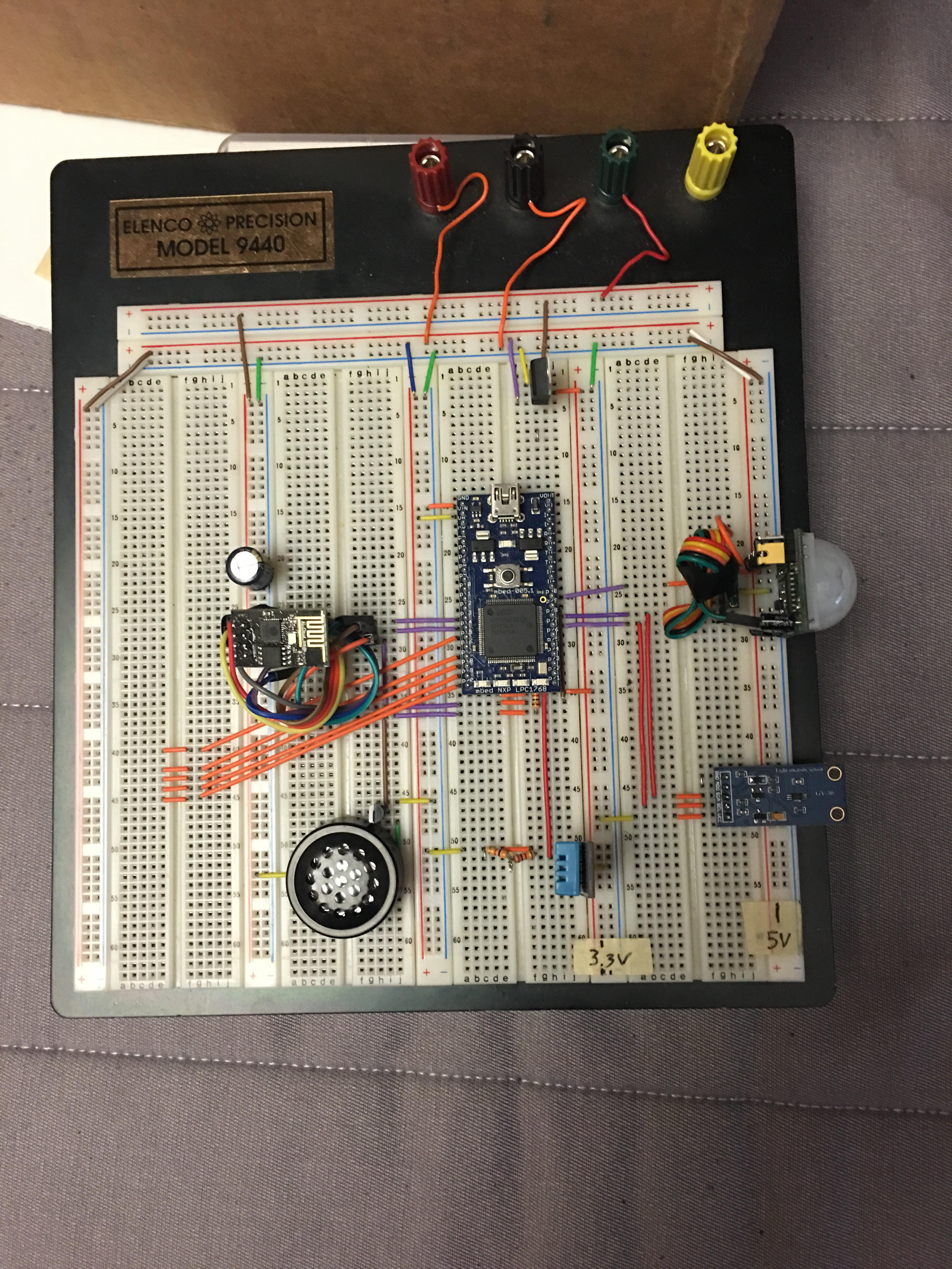
Below is a bird's eye view of the breadboard and power outlet.

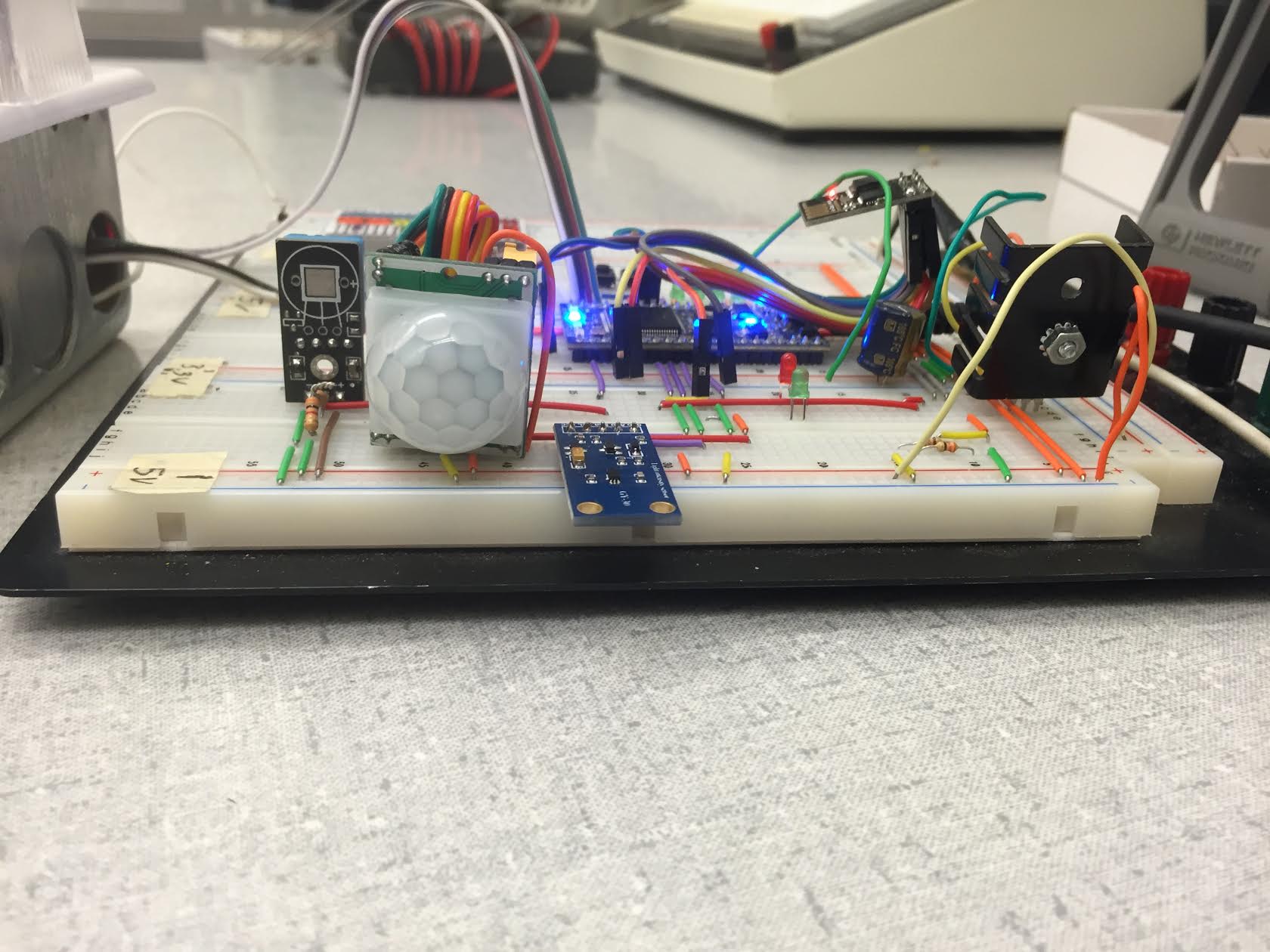
Below is a side view of the breadboard to have a better view of the motion sensor and light sensor.

Please log in to post comments.
