Driving several TLC5917 (SPI driven 8 channels current sink)
The chip
The TLC5917 from Texas Instrument allows to drive devices needing current (50 to 150 mA). The chip is addressable through an SPI bus and can drive 8 channels. It is well suited to drive a 7 segments DEL (8 segments with the dot). Beware than the wiring allows to drive only a 'common anode' type: the height channels are in fact 8 sinks to ground. The SPI interface is managed in a way that allows very easy chaining of several ICs, one for each digit. At the end, driving any number of digits only requires three pins from the mbed: MISO, SCK and a digital pin to acknowledge data.
Wiring
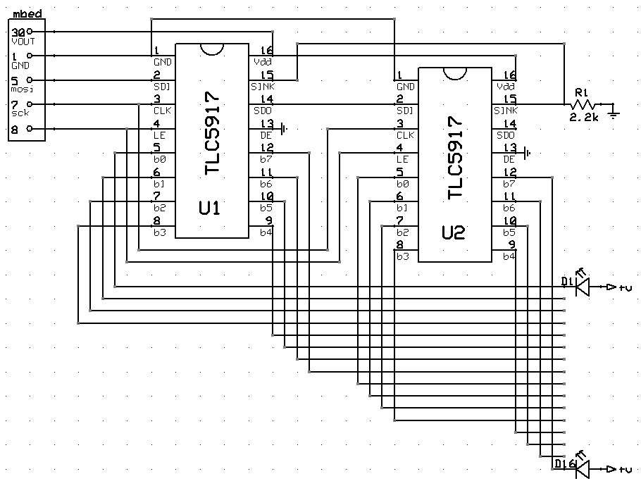
Here is a simple schema of two chained TLC5917:

[EDIT] Bug! : warning, the sinks should not be connected together through a single resistor. (i tried...). Each sink must have its own resistor to ground.
Special notice:
- The OE (Output Enable pin) can be used for advanced functions, in this schema it simply connected to ground to enable ouputs with default factory settings.
- The SPI output (sdo) of the first chip goes in the SPI input of the second chip (sdi).
- All LE pins are connected together.
- The sink goes to ground through a 2.2 K resistor wich is fine for standard LEDS. If the sink was directly connected to ground without resistor, the chip would not obey SPI commands (it is a protection system to avoid shortening LEDs).
SPI communication
The datasheet may be cryptic at first sight, but a bit of experiment unveils the solution: Each data byte arriving in the SDI pin of a chip "pushes" the previously received data byte to the next chip in the chain. So to pass data to chips 1 and 2, transmit first the data byte for chip 2, then data byte for chip 1. The later pushes the first sent byte to the second chip (and so on). When all bytes are in the right chip, the LE pin is pulsed (low to high, then high to low) to signal all chips to use their current data byte to enable/disable channels.
Example to enable pin 0 and 1 on first chip, and pin 3 and 4 of second chip:
spi.write( 6 ); // '6' goes in first chip
spi.write( 3 ); // '3' goes in first chip and pushes '6' in second chip
le = 1; // high pulse
wait_us(10);
le = 0; // back to low
SPI bus sharing
The SPI bus can be shared with some other device. Data received and passed from chip to chip will be ignored as long as the LE pin value remains unchanged. Only the falling edge of the pulse (i.e. high to low signal) will acknowledge the current data.
Complete code example
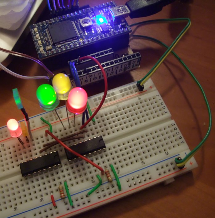
This exemple will blink 6 leds connected to pins 0,1,2 of chip 1 and pins 0,1,2 of chip 2. The blinking will reflect the binary value of a counter cycling from 0 to 63. Blinking is 0.5 seconds long.
A class to wrap the low level communictation. File tlc5917.h: This class allows to drive 1 to 4 tlc5917.
#ifndef TLC5917_H
#define TLC5917_H

#define TLC5917_SET  s_.frequency( 10000000 );  s_.format( 8, 0 );
#define TLC5917_ACK  d_ = 1; wait_us(10); d_ = 0; wait_us(10);

class TLC5917
{
private:
    int     n_;
    SPI&    s_;
    DigitalOut d_;
public:
    TLC5917( SPI& spi, PinName le, int chipCount ) : n_( chipCount ), s_( spi ), d_( le ) {}

    void Clear()
    {
        TLC5917_SET
        d_ = 0;
        wait_us(10);
        for( int i = 0 ; i < n_ ; i++ ) { s_.write( 0x00 ); }
        TLC5917_ACK
    }
    void Write( unsigned char v )
    {
        TLC5917_SET
        s_.write( v );
        TLC5917_ACK
    }
    void Write( unsigned char v0,  unsigned char v1 )
    {
        TLC5917_SET
        s_.write( v1 );
        s_.write( v0 );
        TLC5917_ACK
    }
    void Write( unsigned char v0,  unsigned char v1, unsigned char v2 )
    {
        TLC5917_SET
        s_.write( v2 );
        s_.write( v1 );
        s_.write( v0 );
        TLC5917_ACK
    }
    void Write( unsigned char v0,  unsigned char v1, unsigned char v2, unsigned char v3 )
    {
        TLC5917_SET
        s_.write( v3 );
        s_.write( v2 );
        s_.write( v1 );
        s_.write( v0 );
        TLC5917_ACK
    }
};

#endif
The main program:
#include "mbed.h"
#include "tlc5917.h"

SPI spi( p5, NC, p7 );              // create the SPI port

TLC5917 tlc( spi, p8, 2 );          // create the TLC group, passing  the SPI port,
                                    // the LE pin and the number of connected chips

int main()
{
    tlc.Clear();                    // set all channels to 'open switch'

    int i = 0;                      // the counter

    while( 1 )
    {
        tlc.Write( i & 7, i >> 3 ); // send 3 LSB to chip 1, 3 MSB to chip 2 and ACK pulse
        wait( 0.5 );
        i = (i + 1) & 63;           // increase i and rollover at 64 with simple binary masking
    }
}
The circuit for the sample

Please log in to post comments.
