Heart Rate Sensor
Introduction
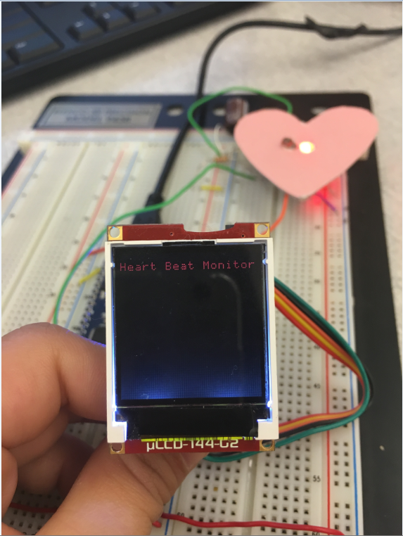
This device measures the heart rate optically and outputs the BPM of the user onto the screen.

Materials Used
- Photo Resistor from SparkFun
- 330 Resistor
- 10k Resistor
- uLCD-144 board
- Red LED
- Wires
- BreadBoard
How It Works
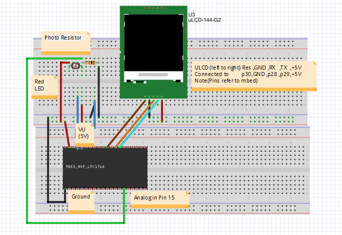
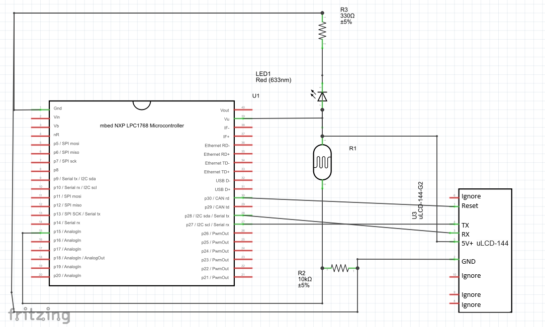
The red LED and the photo resistor should be beside each other when wiring up the circuit (look at pictures for reference). By placing the thumb over the Photo Resistor, the overall resistance of the photoresistor will change. When the blood is pumped through the thumb, It will cause less light to reflect onto the photoresistor. This causes a voltage fluctuation which can be interpreted into BPM by the MBED.
Breadboard

Schematic

Videos Demo
Code
Import programHeartRateMonitor
Optical heart rate monitor using photoresistor and LED to calculate BPM, which is outputted to LCD screen.
1 comment on Heart Rate Sensor:
Please log in to post comments.

Do you have a schematic of the breadboard without the labels on it? They are in the way of some wires, so I don't know how to properly assemble the circuit.