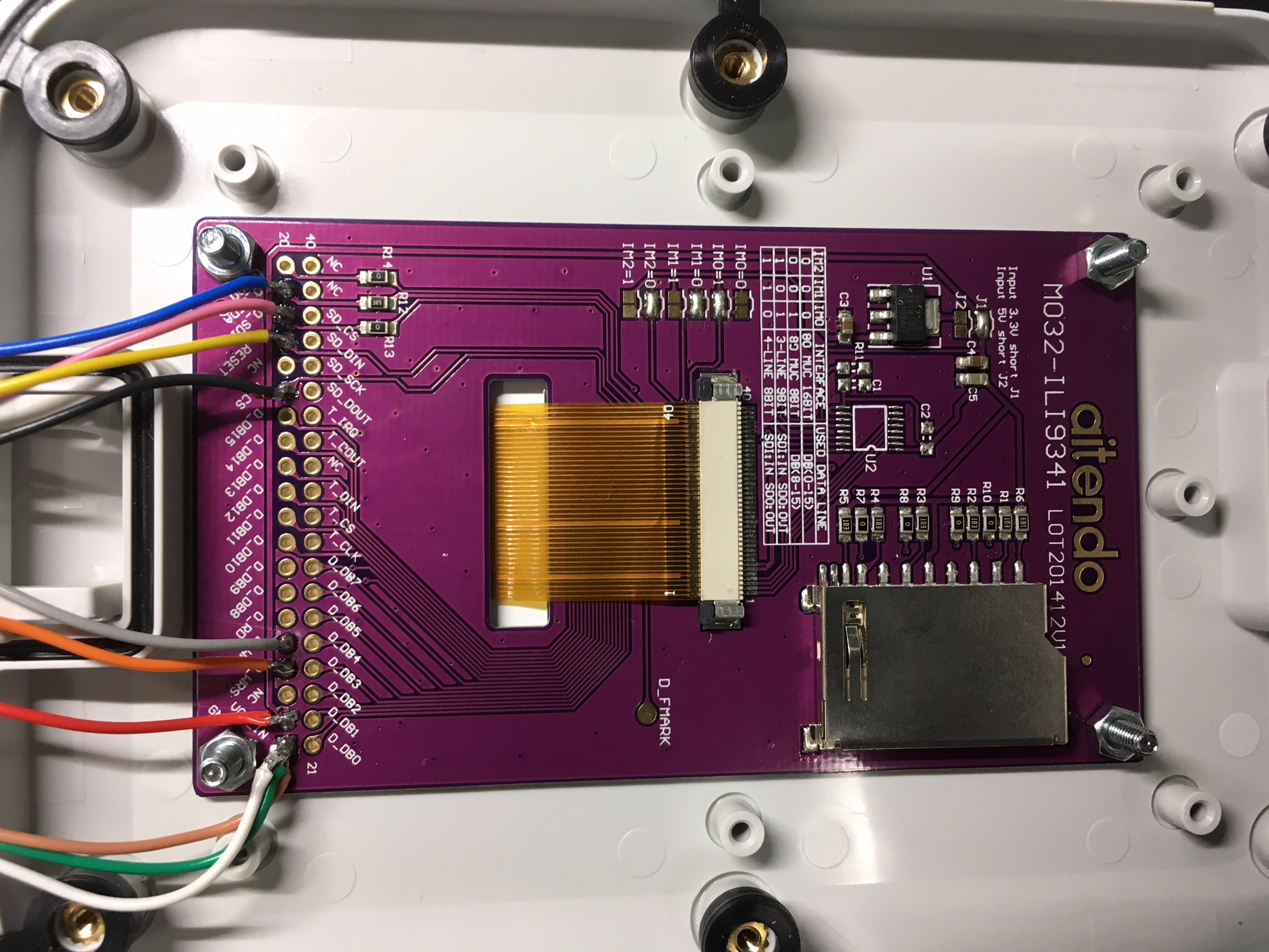
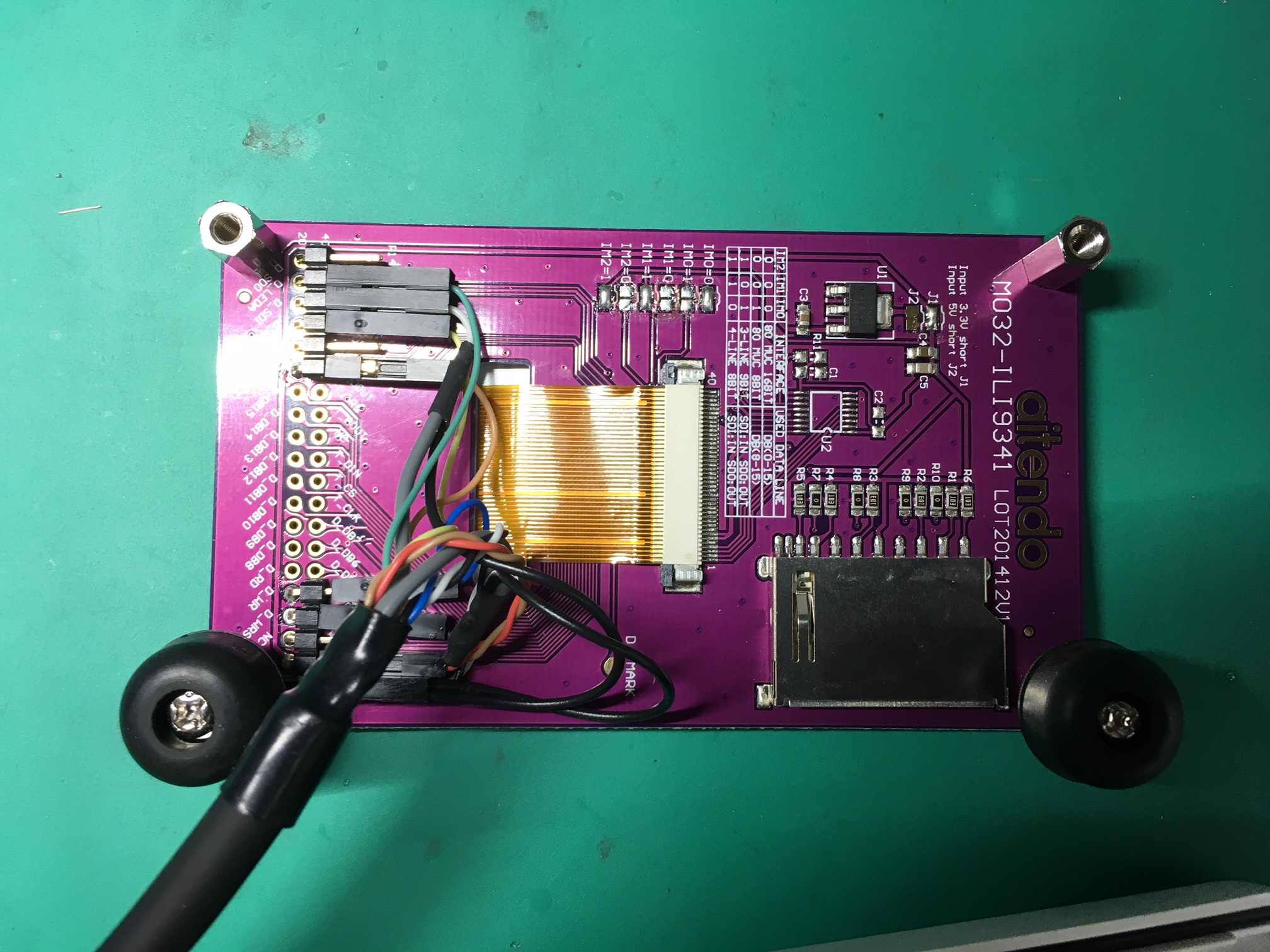
Temporary Connector Reversed Version
Dependencies: UniGraphic mbed vt100
afero_poc15_180403R , J1 のピン配置を反転させたヴァージョンです。
Color2系を使用するためには以下のピンをジャンパで接続してください。
J1-D7 <-> J1-D0
J1-D6 <-> J1-D1
(調査中) また、こちらでテストした範囲では、
FRDM-KL25Z の V3.3 を、Modulo2 の VCC_3V3 ピンに接続してやる必要がありました。
尚、J1-D1, D0 を使用するために UART を無効にしているため
ログは表示されません。
TFTモジュールについて
aitendoのTFTモジュールはデフォルトでは8bit bus モードになっています。

半田のジャンパを変えて、SPIの設定にしてください。

サーミスタについて
POC1.5 では サーミスタは 25℃の時に抵抗値が 50.0kΩになる502AT-11 が
4.95kΩのプルアップ(実際は10kΩx2の並列)で使用されていました。
今回の試作では抵抗値が 10.0kΩの 103AT-11 が
5.1kΩのプルアップで使用されていますので、係数を合わせるために
SMTC502AT-11 のコンストラクタを
R0 = 10.0
R1 = 5.1
B = 3435
T0 = 298.15
で呼ぶように変更しました。
edge_sensor/edge_color.h
- Committer:
- Rhyme
- Date:
- 2018-04-24
- Revision:
- 1:6c54dc8acf96
- Parent:
- 0:0b6732b53bf4
File content as of revision 1:6c54dc8acf96:
#ifndef _EDGE_COLOR_H_
#define _EDGE_COLOR_H_
#include "mbed.h"
#include "edge_sensor.h"
#include "VEML6040.h"

/**
 * edge_color edge_sensor which manages LED and color sensor (VEML6040)
 */

class edge_color : public edge_sensor {
public:
/**
 * constructor
 * @param *sensor VEML6040 object
 * @param *led[] PwmOuts for LEDs
 * @param *pwm[] uint16_t pwm duty values
 */
    edge_color(VEML6040 *sensor, PwmOut *led[], uint16_t *pwm) ;

/**
 * destructor
 */
    ~edge_color(void) ;

/**
 * reset and clear internal values
 */
    virtual void        reset(void) ;

/**
 * prepare at first this was planned to set LEDs
 * before sampling, but turned out to be not neccesarry
 */
    virtual void        prepare(void) ;

/**
 * sample sampling the color value(s) is some what complicated.
 * At first leds are turned on using the pwm values _pwm[].
 * then VEML6040 is triggered with config value, which includes
 * the trigger method and integration time.
 * Wait for the integration time (actually x 1.25 of the value)
 * then acquire the color values from VEML6040 and turn the leds off.
 */
    virtual int        sample(void) ;

/**
 * Deliver the sampled value to the afero cloud.
 */
    virtual int         deliver(void) ;

/**
 * Show the value(s) in the display (TFT)
 */
    virtual void        show(void) ;

/**
 * calibrate: caribrate the led pwm values trying to adjust the measured
 * values to the values given in target[]. Measurements are repeated
 * num_ave+2 times and the minimum and maximum values will be discarded
 * then average values are calculated using the remaining values.
 * @param target[] uint16_t target values for R, G, B measurement
 * @param result[] uint16_t calibrated pwm R,G,B values
 * @param num_ave repeat time for averaging the measurement data
 */
    void        calibrate(uint16_t target[], uint16_t result[], int num_ave) ;

/**
 * request_calibration: set the flag to calibrate next avilable time slot
 */
    void        request_calibration(void) { _calibration_request = 1 ; }

/**
 * calibration_requested
 * @returns if the calibration is due
 */
    int         calibration_requested(void) { return _calibration_request ; }

/**
 * getAveColor
 * @param led[] uint16_t pwm values for R,G,B
 * @param v[]   uint16_t averaged measurement value
 * @param num_ave int    measurment repeat time for averaging
 */
    void        getAveColor(uint16_t led[], uint16_t v[], int num_ave) ;

/**
 * getRGB
 * @param v[] uint16_t measured R,G,B values
 * @returns 0: success non-0: failure
 */
    int        getRGB(uint16_t v[]) ;

/**
 * getConfig
 * @returns config this value is used to trigger VEML6040 measurement
 */
    uint8_t     getConfig(void) { return _sensor_config ; }

/**
 * setConfig
 * @param config uint8_t 8bit value to use trigger VEML6040 measurement
 */
    void        setConfig(uint8_t config) { _sensor_config = config ; }

/**
 * get_pwm_period
 * @returns pwm_period in us
 */
    uint16_t    get_pwm_period(void) { return _pwm_period ; }

/**
 * set_pwm_period
 * @param pwm_period uint16_t pwm period in us
 */
    void        set_pwm_period(uint16_t period) { _pwm_period = period ; }

/**
 * get_pwm_target
 * @returns measurment target value controlled by the pwm
 */
    uint16_t    get_pwm_target(void) { return _pwm_target ; }

/**
 * set_pwm_target
 * @param target uint16_t measurement target value
 */
    void        set_pwm_target(uint16_t target) { _pwm_target = target ; }

/**
 * getR
 * @returns measured value of R
 */
    uint16_t    getR(void) { return _value[0] ; }

/**
 * getG
 * @returns measured value of G
 */
    uint16_t    getG(void) { return _value[1] ; }

/**
 * getB
 * @returns measured value of B
 */
    uint16_t    getB(void) { return _value[2] ; }

/**
 * getPwmR
 * @returns PWM value of R LED
 */
    uint16_t    getPwmR(void) { return _pwm[0] ; }

/**
 * setPwmR
 * @param pwm_r
 */
   void setPwmR(uint16_t pwm_r) { _pwm[0] = pwm_r ; }

/**
 * getPwmG
 * @returns PWM value of G LED
 */
    uint16_t    getPwmG(void) { return _pwm[1] ; }

/**
 * setPwmG
 * @param pwm_g
 */
   void setPwmG(uint16_t pwm_g) { _pwm[1] = pwm_g ; }

/**
 * getPwmB
 * @returns PWM value of B LED
 */
    uint16_t    getPwmB(void) { return _pwm[2] ; }

/**
 * setPwmB
 * @param pwm_b
 */
   void setPwmB(uint16_t pwm_b) { _pwm[2] = pwm_b ; }

/**
 * setLEDs set pwm values to PwmOut pins to drive LEDS
 * @param led_value[] uint16_t pwm values for R, G, B
 */
    void        setLEDs(uint16_t led_value[]) ;

/**
 * setLEDs set pwm values to PwmOut pins to drive LEDS
 * @param r uint16_t pwm value of R LED
 * @param g uint16_t pwm value of G LED
 * @param b uint16_t pwm value of B LED
 */
    void        setLEDs(uint16_t r, uint16_t g, uint16_t b) ;

protected:
    VEML6040    *_sensor ;
    uint8_t     _sensor_config ;
    PwmOut      *_led[3] ;
    uint16_t    _pwm_period ;
    uint16_t    _pwm_target ;
    uint16_t    _value[3] ; /* r, g, b */
    uint16_t    _pwm[3] ;   /* r, g, b */
    uint16_t    _probe ; /* probing value for calibration */
    uint8_t     _calibration_request ;
} ;

extern uint16_t        color0_pwm[3] ;
extern uint16_t        color1_pwm[3] ;
extern uint16_t        color0_target[3] ;
extern uint16_t        color1_target[3] ;

#endif /* _EDGE_COLOR_H_ */
 La Suno