This program connects to a few sensors via I2C and sends the data collected to a WNC Cellular Module which is located on an Avnet WNC-Shield card.
Dependencies: FXOS8700CQ MODSERIAL mbed

Avnet Cellular IoT Instructions
- One problematic area is setting the MY_SERVER_URL. When you copy the URL from the flow, you must make sure the MY_SERVER_URL is also set to the appropriate server. It can be either "run-east.att.io" or "run-west.att.io".
Useful Links
Adding Additional Sensors
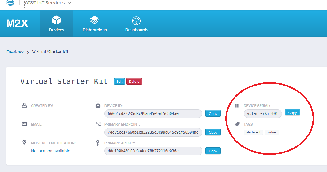
The FLOW_DEVICE_NAME field must contain the name of the instance of the Virtual Starter Kit in FLOW you will be communicating with. Usually this is "vstarterkit001", but if you have problems communicating you can verify this is correct. Note: This device will not be created until you click the “Initialize” input on the Virtual Device tab of the Starter Kit project in FLOW. At that point, it becomes available in M2X and you can see it as the DEVICE SERIAL field under Devices as in the image below.

Sensors: When executing, the FRDM-K64F board uploads sensor measurements to AT&T’s Flow environment every 5 seconds, using the Cellular shield board. You can adjust how often you want to do this by editing the SENSOR_UPDATE_INTERVAL_MS value in the header file.
Temperature and humidity: By default, the board reports readings from the HTS221 temperature and humidity sensor. These two values are sent to the HTTP IN /climate port in FLOW with field names “temp” and “humidity”. Temperature is in degrees Fahrenheit and humidity is a %. This default assignment is: iSensorsToReport = TEMP_HUMIDITY_ONLY;
Accelerometer: If you want to expand and use the onboard motion sensor, you can also send 3-axis accelerometer information from the board as “accelX”, “accelY”, and “accelZ”. This is useful if you want to know the stationary position of the board with regards to gravity, or whether it is in motion. These readings are in g’s. To send these values, change the assignment to: iSensorsToReport = TEMP_HUMIDITY_ACCELEROMETER;
PMOD Sensors: If you have a Silicon Labs sensor module that can plug into the PMOD connector on the Cellular shield, you are able to measure proximity, UV light, ambient visible and infrared light from the Si1145 sensor. This PMOD also has a temperature and humidity sensor, but in this case it is redundant. When enabled, the fields “proximity”, “light_uv”, “light_vis” and “light_ir” are also sent. To enable all these sensors, change the assignment to: iSensorsToReport = TEMP_HUMIDITY_ACCELEROMETER_PMODSENSORS;
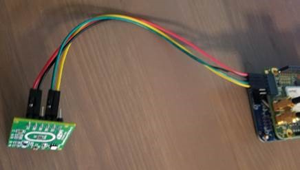
Connecting the PMOD sensors: Because the pinouts do not align, the SiLabs PMOD sensor board cannot be plugged into the J10 PMOD receptacle on the shield directly. The following wiring instructions must be followed:
| Signal | J10 | Shield | PMOD Color in the image below |
|---|---|---|---|
| VCC | Pin 6 | Pin 6 | Red |
| GND | Pin 5 | Pin 5 | Black |
| SDA | Pin4 | Pin 3 | Green |
| SCL | Pin3 | Pin 2 | Yellow |

AT&T M2X and FLOW Instructions
Link to AT&T M2X
Link to AT&T Flow
Avnet WNC-Shield Information
Getting Started with the Avnet WNC-Shield Software
- This project uses Revision 119 of the MBED library because of I2C implementation differences with the tip (Revision 121).
- This project uses Revision 4 of the FXOS8700CQ library for sensors.
Easily Modifiable Parameters
Inside the mbed Avnet_ATT_Cellular_IOT project, the parameters needed to customize your board are in the config_me.h file.
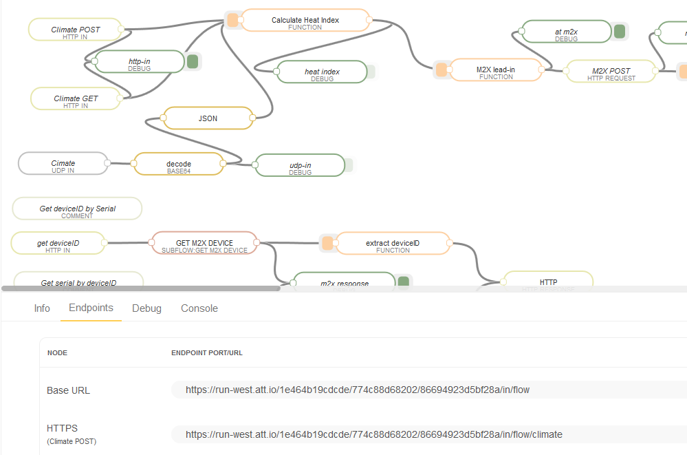
- FLOW parameters: This project assumes you are using a fork of the Starter Kit Base project, which is a reference design created using AT&T’s FLOW (https://flow.att.com) that allows the creation of online virtualization and other IoT functionality. The default parameters in the config_me.h file are done for a specific instance of this project. When you fork the original project, you get your own instance and it will have its own base address. At the bottom of the FLOW environment, when you click on the Endpoints tab, URL information that is specific to your instance is displayed. Of note is the Base URL. In the example below (as in the default mbed project), the Base URL is: https://run-west.att.io/1e464b19cdcde/774c88d68202/86694923d5bf28a/in/flow You have to take note of two parts of this address. The run-west.att.io part is the server URL, and you have to make sure the
- MY_SERVER_URL field in config_me.h matches this. The rest of the base URL, in green above, needs to be pasted into the FLOW_BASE_URL field.
There is also a FLOW_INPUT_NAME field. This should match the name of the HTTP IN port in the FLOW project that you want to send sensor data to. The default is "/climate", as in the FLOW image below.

Where is the Binary I compiled
When the COMPILE button is pressed, it compiles your project and links it. The result is placed in the DOWNLOAD folder you use when downloading files from the Internet. It will be called AvnetATT_shape_hackathon_K64F.bin.
Additional Information on Compiling/Configuring
Comprehensive instructions can be found at: Quick Start Instructions
HTS221.h
- Committer:
- root@developer-sjc-indigo-compiler.local.mbed.org
- Date:
- 2017-12-11
- Revision:
- 83:55778a2d5c5e
- Parent:
- 68:6e311c747045
File content as of revision 83:55778a2d5c5e:
/* ===================================================================
Copyright © 2016, AVNET Inc.

Licensed under the Apache License, Version 2.0 (the "License");
you may not use this file except in compliance with the License.
You may obtain a copy of the License at

   http://www.apache.org/licenses/LICENSE-2.0

Unless required by applicable law or agreed to in writing,
software distributed under the License is distributed on an
"AS IS" BASIS, WITHOUT WARRANTIES OR CONDITIONS OF ANY KIND,
either express or implied. See the License for the specific
language governing permissions and limitations under the License.

======================================================================== */

#ifndef HTS221_H_
#define HTS221_H_

class HTS221 {
public:
    HTS221(void);
    int begin(void);
    int activate(void);
    int deactivate(void);

    int bduActivate(void);
    int bduDeactivate(void);

    int readHumidity(void);
    double readTemperature(void);
private:
    int storeCalibration(void);
    unsigned char _h0_rH, _h1_rH;
    unsigned int  _T0_degC, _T1_degC;
    unsigned int  _H0_T0, _H1_T0;
    unsigned int  _T0_OUT, _T1_OUT;
    double _temperature;
    int _humidity;
    unsigned char _address;

    unsigned char readRegister(unsigned char slaveAddress, unsigned char regToRead);
    int writeRegister(unsigned char slaveAddress, unsigned char regToWrite, unsigned char dataToWrite);
};

#define HTS221_ADDRESS     0xBF

//Define a few of the registers that we will be accessing on the HTS221
#define WHO_AM_I           0x0F
#define WHO_AM_I_RETURN    0xBC //This read-only register contains the device identifier, set to BCh

#define AVERAGE_REG        0x10 // To configure humidity/temperature average.
#define AVERAGE_DEFAULT    0x1B

/*
 * [7] PD: power down control
 * (0: power-down mode; 1: active mode)
 *
 * [6:3] Reserved
 *
 * [2] BDU: block data update
 * (0: continuous update; 1: output registers not updated until MSB and LSB reading)
The BDU bit is used to inhibit the output register update between the reading of the upper
and lower register parts. In default mode (BDU = ?0?), the lower and upper register parts are
updated continuously. If it is not certain whether the read will be faster than output data rate,
it is recommended to set the BDU bit to ?1?. In this way, after the reading of the lower (upper)
register part, the content of that output register is not updated until the upper (lower) part is
read also.
 *
 * [1:0] ODR1, ODR0: output data rate selection (see table 17)
 */
#define CTRL_REG1          0x20
#define POWER_UP           0x80
#define BDU_SET            0x4
#define ODR0_SET           0x1   // setting sensor reading period 1Hz

#define CTRL_REG2          0x21
#define CTRL_REG3          0x22
#define REG_DEFAULT        0x00

#define STATUS_REG         0x27
#define TEMPERATURE_READY  0x1
#define HUMIDITY_READY     0x2

#define HUMIDITY_L_REG     0x28
#define HUMIDITY_H_REG     0x29
#define TEMP_L_REG         0x2A
#define TEMP_H_REG         0x2B
/*
 * calibration registry should be read for temperature and humidity calculation.
 * Before the first calculation of temperature and humidity,
 * the master reads out the calibration coefficients.
 * will do at init phase
 */
#define CALIB_START        0x30
#define CALIB_END          0x3F
/*
#define CALIB_T0_DEGC_X8   0x32
#define CALIB_T1_DEGC_X8   0x33
#define CALIB_T1_T0_MSB    0x35
#define CALIB_T0_OUT_L     0x3C
#define CALIB_T0_OUT_H     0x3D
#define CALIB_T1_OUT_L     0x3E
#define CALIB_T1_OUT_H     0x3F
 */

#endif
 Avnet ATT WNC 14A2A Cellular IoT Kit