DVK-NCS36510-MBED-GEVB
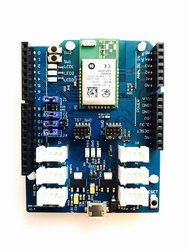
The DVK-NCS36510-MBED-GEVB is a development and evaluation board for the ON Semiconductor Ultra-low Power 802.15.4 RF Transceiver System On Chip NCS36510.
Platform Overview
The DVK-NCS36510-MBED-GEVB is a development and evaluation board for the ON Semiconductor Ultra-low Power 802.15.4 RF Transceiver System On Chip NCS36510.
The NCS36510 is added to the mbed board as an RF module which is pre-certified for FCC, ETSI, IC, and MIC.
With Arduino compatible and Grove connector add-ons this platform board can be used to create ultra-low power wireless sensor nodes using any 802.15.4 protocol such as Thread and ZigBee.
Onboard active current measurement circuits allow the current consumption to be measured in nearly real time. An optional battery holder also creates the opportunity for battery powered sensor nodes using the mbed platform.
Pin Diagram(s)


Features
- NCS36510 MCU
- High performance ARM® Cortex™-M3 Core
- 32MHz clock, 48kB RAM, 2 banks of 320kB FLASH (640kB total)
- SPI (2)
- I2C (2)
- UART (2)
- PWM (1)
- ADC (10b, 4 input MUX)
- GPIO (18)
- NCS36510 Radio
- 2.4 GHz IEEE 802.15.4−2006 RF Transceiver
- PHY/MAC layers pre-certified for ZigBee
- RF Module pre-certified for FCC, IC, ETSI, and MIC
- Hardware accelerated MAC
- Hardware accelerated security
- AES 128/256 Encryption Engine
- True Random Number Generator
- NCS36510 Onboard Sensors
- Power supply voltage
- Internal temperature sensor
- mbed Board Features
- Arduino shield compatible
- Grove connectors
- Analog (2)
- Digital (2)
- I2C (2)
- User switch (2)
- User LED (3)
- CMSIS-DAP debug support
- SWD debug support
- Current consumption measurement circuits
- Footprint for battery holder
- Push button reset
- Pre-certified NCS36510 RF module
Getting Started with mbed
1. Connect your microcontroller to a PC
Use a USB cable to connect your mbed to a PC. The status light will come on, indicating it has power. After a few seconds of activity, the PC will recognise the mbed Microcontroller as a standard USB drive.
 Windows 7 example |
2. Click the MBED.HTM link to get logged in
Go to the new USB Drive, and click MBED.HTM to open it in a web browser.
If you do not have an mbed account, choose "Signup", and create your mbed Account. Otherwise, log in with your normal username and password.
This will give you access to the website, tools, libraries and documentation.
PC Configuration
Your mbed Microcontroller can appear on your computer as a serial port. On Mac and Linux, this will happen by default. For Windows, you need to install a driver:
Windows
See Windows-serial-configuration for full details about setting up Windows for serial communication with your mbed Microcontroller
From a host PC to communicate with mbed you will need a terminal application. This allows the mbed Microcontroller to print to your PC screen, and for you to send characters back to your mbed.
- Terminals - Using Terminal applications to communicate between the Host PC and the mbed Micrcontroller
Some terminal programs (e.g. TeraTerm) list the available serial ports by name. However, if you do need to know the identity of the serial port so that you can attach a terminal or an application to it:
| Windows | Mac | Linux | ||||
| Find the identity of the COM port by opening ''Device Manager''. To do this navigate ''Start -> Control Panel -> System -> Hardware -> Device Manager''. | To find the device name under Mac OS X, use the command ''ls /dev/tty.usbmodem*'' | To find the device name under Linux, use the command ''ls /dev/ttyACM*'' | ||||
 |  |  |
Downloading A program
1. Save a program binary (.bin) to the Platform
Download the appropriate "Hello World!" binary:
- NCS36510: mbed-os-example-blinky.bin
Note: the source code for this program will be seen in the next section.
Save the program binary file to your mbed Microcontroller Disk, just like you would with a normal USB disk. The Status LED (see picture below) will flash as the PC writes the file to the Microcontroller disk.
2. Press the Reset Button
When the Reset Button in pressed (see picture below), the microcontroller will be reset and the last programmed application will begin to run.

3. Hello World!
The Microcontroller is now running the program; flashing LED1 forever! If you reset the Microcontroller, or disconnect and reconnect the power, the program will simply restart.
Example Applications
Hello World! (LED Blinky)
[Repository '/teams/mbed-os-examples/code/mbed-os-example-blinky/' not found]
Adafruit ST7735 TFT Shield mbed Example
Import programmbed-TFT-example-NCS36510
mbed example application for the Adafruit ST7735 TFT Shield, which implements SPI connections to the TFT shield and SD card, as well as an ADC to read from the analog in pins.
Last commit 27 Feb 2017 by  ON Semiconductor
Seeed Grove OLED mbed Example
Import programmbed-OLED-example-NCS36510
Seeed Grove OLED example program for mbed on NCS36510
Last commit 25 Jan 2017 by ON Semiconductor
Seeed Grove Chainable LED mbed Example
Import programmbed-Chainable-LED-example-NCS36510
Grove Chainable LED example application for ON Semiconductor NCS36510
Last commit 25 Jan 2017 by ON Semiconductor
Using the Online Compiler
Follow the guide to creating your own programs using the online compiler
Offline Development
Using the mbed Command-Line-Interface Offline Toolchain
For developers that would like to build applications using an offline toolchain, ARM has provided the mbed CLI. This command-line tool has all of the functionality of the online compiler, and adds the flexibility of using any desired code editor.
To get started, install the mbed CLI toolchain using the installer provided here.
For reference on how to use the mbed CLI, see the documentation here.
Information
From mbed OS version 5.5.5 and higher, the mbed CLI build system outputs a .hex file instead of a .bin file. In this case DAPLink version 243 or higher must be used (See DAPLink section below)
Debugging with Eclipse and PyOCD
Eclipse can be used to debug mbed OS 5 projects. For instructions on how to set up Eclipse for debugging the NCS36510 using PyOCD, see this wiki page.
Debugging with IAR EWARM IDE
Compiling and debugging mbed OS 5 projects with the NCS36510 is supported in IAR Embedded Workbench for ARM v7.80. 2
To export an existing mbed OS project to IAR, navigate in the command line to the project directory, then use mbed CLI with the following the command:
mbed export -m NCS36510 -i IAR
This will generate, among other files, an IAR EWARM workspace file. Double-clicking this file will open the project in IAR EWARM. Prior to compiling or debugging, extra steps are required. In EWARM, right click on the project in the left-hand column, and open its properties dialogue. Then use this documentation to configure the project for building and debugging.
Note
As shown in the image below, the NCS36510 has two 320 kB banks of flash. Under default operation, only a single bank of flash is programmed, with the second being available for over-the-air update images to be stored.

Several mbed applications, however, require more flash memory for program code. In order to compile applications with code size up to 640 kB, the following conditions must be met:
1. mbed OS version 5.5.5 or greater must be used
2. The IAR 7.80.2 compiler must be used.
3. DAPLink version 243 or higher (See DAPLink section below)
If the above conditions are met, the application may be compiled with the mbed CLI, using the following command:
mbed compile -m NCS36520 -t IAR
Powering the Board with the Vin Pin
At times, it is desired to test the board without being powered via the USB cable. In this case, the board can be powered via the Vin pin. To enable this mode of operation, move the headers J3 and J4 as shown in the pictures below:
USB Powered Mode:

External Powered Mode:

Technical Reference
Power
- USB powered or 4.5v - 9v on Vin pin
- Current (active): < 20 mA
- Current (sleep): < 1 uA (switching regulator)
- 3.3v regulated output on VOUT to power peripherals
- 5.0v from USB available on 5v (only available when USB is connected unless extra regulator is added!)
- Digital IO pins are 3.3v, 4mA each
Board Schematic Files
Data Sheets
Daplink Firmware Updates
Please see the dedicated wiki page
You need to log in to post a discussion
Board Partner

ON Semiconductor
ON Semiconductor (Nasdaq: ON) is a leading provider of power efficient semiconductor solutions to customers in the power supply, automotive, communications, computer, consumer, medical, wireless, mobile phone, industrial and military/ aerospace markets.
Example programs