You are viewing an older revision! See the latest version
Text LCD Enhanced
This page describes an enhanced forked version of the basic driver code library for Text LCD panels using the 4-bit interface of the HD44780 LCD display controller.

Note that there are many HD44780 compatible LCD controllers around (e.g. KS0066, ST7066, SPLC780, SED1278, LC7985A, NT7603, AIP31066). There are also controllers available that are compatible and provide additional features like an increased number of segment drivers for more characters or internal LCD contrast voltage generators (e.g. KS0073, KS0078, ST7036, SSD1803). Several other types of displays use controllers that are compatible with the HD44780 to allow an easy transition, for example OLED drivers such as the WS0010 and US2066. The library controls the HD44780 through a 4-bit bus either directly or by using SPI or I2C portexpanders. Several compatible controllers also have native support for SPI and/or I2C serial interfaces in addition to, or instead of, the parallel bus (eg ST7032i, ST7036i, ST7070, SSD1803, AIP31068, PCF211X, AC780). The enhanced TextLCD library supports some of these devices.
New features
- Support for more LCD types
- TextLCD::LCD8x1 8x1 LCD panel
- TextLCD::LCD8x2 8x2 LCD panel
- TextLCD::LCD8x2B 8x2 LCD panel (actually 16x1 in different layout)
- TextLCD::LCD12x2 12x2 LCD panel
- TextLCD::LCD12x4 12x4 LCD panel
- TextLCD::LCD12x3D 12x3 LCD panel (for PCF2116 controller)
- TextLCD::LCD12x3D1 12x3 LCD panel (alternate for PCF2116 controller)
- TextLCD::LCD12x4D 12x4 LCD panel (for PCF2116 controller)
- TextLCD::LCD16x1C 16x1 LCD panel (actually 8x2 in different layout)
- TextLCD::LCD16x2 16x2 LCD panel (default)
- TextLCD::LCD16x3F 16x3 LCD panel (actually 24x2 in different layout)
- TextLCD::LCD16x3G 16x3 LCD panel (for ST7036 controller)
- TextLCD::LCD16x4 16x4 LCD panel
- TextLCD::LCD20x2 20x2 LCD panel
- TextLCD::LCD20x4 20x4 LCD panel
- TextLCD::LCD20x4D 20x4 LCD panel (for SSD1803 controller)
- TextLCD::LCD24x2 24x2 LCD panel
- TextLCD::LCD24x4D 24x4 LCD panel (for KS0078 controller)
- TextLCD::LCD40x2 40x2 LCD panel
- TextLCD::LCD40x4 40x4 LCD panel (with two controllers)
- Support for Backlight control
- Support for Cursor and/or Blinking current character
- Support for User Defined Characters to display special symbols
- Improved methods to get and set the memory address of the current character
- Support for I2C PCF8574 or PCF8574A Portexpander, the MCP23008 Portexpander or a SPI Portexpander as alternative interface to save on mbed pins
- Support for some controllers with native I2C or SPI interfaces to save on mbed pins.
- Support for setting LCD Contrast and/or Powerdown mode on controllers which provide that option.
- Support for Icons on controllers which provide that option.
- Support for blinking UDCs and/or Icons on controllers which provide that option.
Revisions
Refactoring (April 2014)
TextLCD has been refactored to fix an issue with recent mbed libs and pins that are defined as NC by default. The change requires that the declaration of the SPI and I2C versions in user code needs a small modification: declare these as TextLCD_SPI() or TextLCD_I2C respectively. See example code below.
Native I2C and SPI interface support (June 2014)
TextLCD has been extended with support for controllers that have native I2C or SPI interfaces (eg ST7032i). Declare these as TextLCD_SPI_N() or TextLCD_I2C_N respectively. See example code in header file.
LCDType enhancements (June 2014, Aug 2014, Sept 2014, Oct 2014)
TextLCD has been extended with additional LCDTypes for 3 or 4 line displays that are supported by some controllers (PCF211X, KS0078, ST7036 and SSD1803). These LCDTypes use different addressing schemes and are identified by a letter added to the LCDtype enumerator. See example code in header file.
TextLCD has been extended with additional controllers (US2066/SSD1311 (OLED), PT6314 VFD). Added support for blinking UDCs and Powerdown on controllers with these capabilities.
Added support for setting orientation (upside down), added support for double height lines and 16 UDCs on controllers with these features. Moved UDC defines to separate file and added separate file to configure features and allow some control over memory footprint.
Added support for AC780. Added some I2C expander module types and added support for modules that use inverted logic for backlight control.
LCDType enhancements (Nov 2014)
Added ST7070 and KS0073 support, added setIcon(), clrIcon() and setInvert() method for supported controllers.
Background
The LCD driver HD44780 is designed for 2 rows of max 40 chars. Note that it needs some support segment drivers to control that maximum number of chars, without those external drivers the device can only display 2x8 chars using its own 16 common drivers and 40 segment drivers.

The default addressing scheme is as follows:
The address for the first char on the first line is 0x00. The address for the first char on the second line is 0x40. Four line displays are generally created by splitting the two line display and arranging the two parts above each other. For example 2x40 is split in 2 parts of 2x20 and arranged as 4x20. The addresses for the 3rd and 4th line just continue where the split was made:
- The address for the first char on the first line is 0x00, the last char is 0x13.
- The address for the first char on the second line is 0x40, the last char is 0x53.
- The address for the first char on the third line is 0x14, the last char is 0x27.
- The address for the first char on the fourth line is 0x54, the last char is 0x67.
The original TextLCD lib uses the address(column,row) method to return the memory address. However, the method adds 0x80 to the returned addressvalue to include the 'set display datamemory address' command. This is rather confusing when you try to make sense of the actual address. See discussion here.
The enhanced library provides the getAddress(column,row) method to return the correct address. The original method is still provided for compatibility reasons.
TextLCD has been extended with additional LCDTypes for 3 or 4 line displays that are supported by some controllers (eg PCF211X, KS0078, SSD1803). These LCDTypes use a different addressing scheme and are identified by letter 'D' added to the LCDtype enumerator. The addressing scheme for such a 12x4 display is:
- The address for the first char on the first line is 0x00, the last char is 0x0B.
- The address for the first char on the second line is 0x20, the last char is 0x2B.
- The address for the first char on the third line is 0x40, the last char is 0x4B.
- The address for the first char on the fourth line is 0x60, the last char is 0x6B.
These 3 line displays are configured as 4 line displays where last or first line is not shown. This mode is selected by choosing LCDType 12x3D or 12x3D1 respectively.
The addressing scheme for the 24x4 display is similar in the sense that the address of the last character on first line is 0x17, for the second line it is 0x37 etc.
There is yet another format for 3 line displays in which the first half of the third line is actually a continuation of the first line and second half of the third line is a continuation of the second line. TextLCD has been extended to support this type. These LCDTypes use a different addressing scheme and are identified by letter 'F' (eg LCDType 16x3F, which is actually a 24x2).
TextLCD has also been extended with additional LCDTypes for 3 line displays supported by the ST7036 controller. This LCDType use a different addressing scheme which is identified by letter 'G' added to the LCDtype enumerator. The addressing scheme for such a 16x3 display is:
- The address for the first char on the first line is 0x00, the last char is 0x0F.
- The address for the first char on the second line is 0x10, the last char is 0x1F.
- The address for the first char on the third line is 0x20, the last char is 0x2F.
- Note1: The HD44780 is pretty flexible and variations of driverhardware and LCD glass layout may result in differences. The 40x4 line displays actually use two controllers (in 2x40 mode) with separate enable pins.
- Note2: The HD44780 supports left/right shifting of memory locations (address) wrt displayposition. That changes the address of the char that is shown on a displaylocation. This is pretty confusing and leads to inconsistencies between displaytypes of different numbers of lines or characters/line. The enhanced TextLCD lib therefore does not use this feature.
LCD wiring
The new lib supports several ways of connecting with mbed:
- Direct connection with mbed pins using a parallel bus (same as original TextLCD)
- Serial connection using mbed I2C bus and a PCF8574/PCF8574A or MCP23008 portexpander
- Serial connection using mbed SPI bus and a 74595 shiftregister
- Serial connection using mbed I2C or SPI bus and a controller that has native support for I2C or SPI (eg ST7032i)
Pinout
The most commonly found connector on LCDs has 14 pins in a single row or as 2x7 pins. Note there may also be 2 additional pins for the backlight. The pinout for the LCD connector is fairly standard. However, exceptions are known. Always check the datasheet and verify by visual or conductivity testing of the GND pin. GND is normally connected to the metal frame around the LCD glass.
The 'standard' pinout has been used in the tables below.

Contrast Voltage
The contrast VO pin may have different behaviour on different displays, so you may need to experiment for your display to see anything. The contrast voltage depends on the type of Liquid Crystal material that is being used for the display, it does not depend on the controller type. Obviously the controller has a certain voltage range it can withstand, but as long as you stay within its specs there will not be a problem. You will see that LCDs suitable for an extended temperature range often use larger and/or negative contrast voltages. The same is true for displays that have higher refresh frequencies, such as graphics displays. The contrast voltage is normally given or referenced against the positive powersupply (so NOT with reference to GND).
For example, the spec sheet for the display may say : LCD Driving Supply voltage Vdd - Vee (so referenced against powersupply Vdd, which is 5V): -0.3...13V. That translates to 5V-0.3V = 4.7V down to 5V-13V= -8V (now referenced against GND). The typical LCD operation voltage for this display is given as 4.2V..6.4V. This is again relative to Vdd so 0.8V..-1.4V relative to GND.
The optimal setting for the contrast voltage depends on the ambient temperature and the viewing angle.
Adjustable contrast can be achieved with a 10k trim-pot in a voltage divider configuration: one side to Vcc, other side to GND, wiper to VO. Adjust until you see a top line of solid rectangles, then back off until they just disappear. Most LCDs should be set at around 0.5 V for best results. The display goes dark or light for the largest part of the potmeter range and does not show much change in contrast anymore. Displays powered at 3V3 instead of 5V may also need a (small) negative voltage at VO. One side of the trimpot is connected to the negative voltage instead of GND in that case.
Standard or fully compatible controllers should at least show a top row of black rectangles as soon as power and contrast voltage are OK even without any other connections or without running any software. However, note that some (almost) compatible controllers remain in powerdown mode and must be fully initialised before showing anything.
Enhanced controllers which have LCD voltage generators onboard will usually support programmable contrast. This means you will not see anything on screen until the settings are correct! Some OLED displays will default to an average contrast.
Supply Voltage
The specsheet of the standard HD44780 says that powersupply should be between 4.5V and 5.5V. These displays should connect pin 2 VCC to 5V as shown in the tables below. The datapins will typically work with the 3V3 logiclevels provided by the processor since the minimum threshold for logic high is 2V2. Powersupply range is often less tolerant. More recent HD44780 compatible controllers may also run on 3V3 powersupply. Check the datasheet for details.
Use decoupling capacitors (100uF parallel to 100nF) on your 5V or 3V3 powersupply for the display, especially when the power is provided my mbed. This will help avoid brief powerline dips which could lead to distorted characters on the display.
Parallel bus wiring
| TextLCD pins | mbed pins |
|---|---|
| p1 GND | p1 0V |
| p2 VCC | p39 5V Vout |
| p3 VO | via wiper of 10k pot |
| p4 RS | p15 |
| p5 RW | p1 0V |
| p6 E | p16 |
| p7 D0 | not connected |
| p8 D1 | not connected |
| p9 D2 | not connected |
| p10 D3 | not connected |
| p11 D4 | p17 |
| p12 D5 | p18 |
| p13 D6 | p19 |
| p14 D7 | p20 |
The mbed pins can be supplied in the TextLCD constructor and may be changed. Some LCD displays will work OK with a 3V3 powersupply voltage. You may have to provide a small negative Vo in that case to get good contrast. A simple schematic is here.
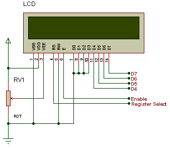
Serial I2C bus expander wiring
The advantage of using the I2C bus and a PCF8574/PCF8574A or MCP23008 portexpander is that you save on mbed pins. This is even more true when you use the bus anyhow for other purposes. The small disadvantage that the I2C may be slower than a parallel bus is not a big problem for a slow device like a text display.
| TextLCD pins | PCF8574 pins | mbed pins |
|---|---|---|
| p1 GND | p8 0V | p1 0V |
| p2 VCC | p16 Vcc | p39 5V Vout |
| p3 VO | via wiper of 10k pot | not connected |
| p4 RS | p9 P4 | not connected |
| p5 RW | p8 0V | p1 0V |
| p6 E | p10 P5 | not connected |
| p7 D0 | not connected | not connected |
| p8 D1 | not connected | not connected |
| p9 D2 | not connected | not connected |
| p10 D3 | not connected | not connected |
| p11 D4 | p4 P0 | not connected |
| p12 D5 | p5 P1 | not connected |
| p13 D6 | p6 P2 | not connected |
| p14 D7 | p7 P3 | not connected |
| not connected | p11 P6 | not connected |
| not connected | p12 P7 | not connected |
| not connected | p1 A0 GND or Vcc | not connected |
| not connected | p2 A1 GND or Vcc | not connected |
| not connected | p3 A2 GND or Vcc | not connected |
| not connected | p15 SDA | p9 or p28 |
| not connected | p14 SCL | p10 or p27 |
The mbed I2C bus must be supplied in the TextLCD constructor and may be changed (p9,p10) or (p28,p27). Note that you must provide pullup Rs of about 4K7. PCF8574 addresspins (p1,p2,p3) must be strapped to GND or Vcc to set the deviceAddress. That address must also be supplied in the LCDText constructor. The PCF8574 supports 8 different addresses (0x40..0x4E). The PCF8574A is similar but has a different baseaddress (0x70..0x7E). So in total you can connect upto 16 LCDs to one I2C bus!
- Note1: Several other vendors supply full clones of the PCF8574 (eg Texas Instruments). The lib now also supports the MCP23008 portexpander. This device has some different features and it must be selected by activating the #define MCP23008 in TextLCD_Config.h.
- Note2: The spare pin D7 on the PCF8574 is available to control the LCD Backlight.
- Note3: You can change the wiring connections between the PCF8574 pins and the LCD. Just update the appropriate pin mapping definitions in TextLCD_Config.h.
- Note4: You can roll-your-own PCF8574 interface or try to find one of the ready made modules on ebay. Search for TWI or I2C and LCD. The boards are all based on the same concept, but there are differences: pinmapping between serial port expander pins and LCD controller, slaveaddress hardwired of selectable by jumpers, solderbridges or a switch, support for backlight control, pull-up resistors for SDA/SCL onboard or not present.
- Note5: Predefined mappings are provided for a DEFAULT version (used in wiring table below) and for several others such as the LCD2004 module from DFROBOT and for a very nice combination of SPI/I2C portexpander by Adafruit. This hardware supports both an I2C expander (MCP23008) and an SPI expander (74595) selectable by a jumper.
Find the following #defines in TextLCD_Config.h to select the appropriate module version.
//Pin Defines for I2C PCF8574/PCF8574A or MCP23008 and SPI 74595 bus expander interfaces
//LCD and serial portexpanders should be wired accordingly
//
//Select Hardware module (one option only)
#define DEFAULT        1
#define ADAFRUIT       0
#define DFROBOT       0
#define YWROBOT      0
#define GYLCD            0
#define SYDZ               0
When the DEFAULT wiring is selected you will also have the additional option to select either the PCF8574 or the MCP23008 expander. The predefined definitions include an option that deals with modules that use inverted logic for backlight control.
Example of a ready made I2C expander for LCDs

Example schematic of homemade I2C expander for LCDs

Serial SPI bus expander wiring
The advantage of using the SPI bus rather than I2C is that the 74595 shiftregister is cheaper than a PCF8574. Disadvantages are that it needs more pins (MOSI, SCLK and CS). You also need a separate CS for every new device since SPI does not support a slaveAddress.
| TextLCD pins | 74595 pins | mbed pins |
|---|---|---|
| p1 GND | p8 0V | p1 0V |
| p2 VCC | p16 Vcc | p39 5V Vout |
| p3 VO | via wiper of 10k pot | not connected |
| p4 RS | p4 Q4 | not connected |
| p5 RW | p8 0V | p1 0V |
| p6 E | p5 Q5 | not connected |
| p7 D0 | not connected | not connected |
| p8 D1 | not connected | not connected |
| p9 D2 | not connected | not connected |
| p10 D3 | not connected | not connected |
| p11 D4 | p15 Q0 | not connected |
| p12 D5 | p1 Q1 | not connected |
| p13 D6 | p2 Q2 | not connected |
| p14 D7 | p3 Q3 | not connected |
| not connected | p10 nMR Vcc | p39 5V |
| not connected | p11 SHCP | p7 or p13 SCK |
| not connected | p12 STCP | p8 CS |
| not connected | p14 DS | p5 or p11 MOSI |
| not connected | p13 nOE GND | p1 0V |
The mbed SPI bus must be supplied in the TextLCD constructor and may be changed (p5,NC,p7) or (p11,NC,p13). You must also provide a CS pin. A simple schematic is here.
- Note1: The 74HC595 should work on 3V3, but 5V is the prefered supplyvoltage
- Note2: The spare pin D7 on the 74HC595 is available to control the LCD Backlight.
- Note3: You can change the connections between the 74595 pins and the LCD. Just update the appropriate pin definitions in TextLCD_Config.h
Native Serial I2C or SPI bus wiring
The SPI port on controllers with native '4 wire' SPI support needs MOSI, SCK, CS and RS pins on the mbed side. Optionally you may connect a Backlight control pin (BL). The default controller type is ST7032i running on 3V3 and using the internal voltage booster. Some devices also use a native '3 wire' SPI interface which needs MOSI, SCK and CS on the mbed side. The RS bit (to select between Data and Command) is transmitted as bit 9 of the SPI communication. This mode is used by AIP31068 and other controllers. The enhanced TextLCD lib provides code for this device, but note that the current mbed libs only support 9 bit SPI messages for the NXP platforms. To make things even more complicated, some controllers (eg WS0010) use a 10 bit 3 wire SPI mode. Again, the code is included in the lib, but will only work on the NXP mbed. Finally there are some controllers (eg SSD1803) that use a 3 wire SPI interface to send a 24 bit message. The RS and RW bit are encoded in the message. This message is broken down into 3 messages of 8 bit each, which means all mbeds can support it. The ST7070 and some other devices also use a '3 wire, 8 bit' SPI interface which needs MOSI, SCK and CS on the mbed side. There is no RS bit and Data exchange is started by first sending a special Command followed by a number of databytes. This mode is supported but is not very efficient wrt communication time.
The I2C port on controllers with native I2C support needs SCL and SDA pins on the mbed side. Optionally you may connect a Backlight control pin (BL). The default controller type is ST7032i running on 3V3 and using the internal voltage booster. Only one slaveaddress is supported for the ST7032i. That means you can connect only one device to the I2C bus. Some other controllers support either 2 (eg PCf21xx, SSD1803) or up to 4 slaveaddresses (eg ST7036, AC780). Note that some I2C controllers dont support the I2C Ack. This applies sometimes for Chip-on-Glass (COG) devices due to the electrical characteristics of that technology. The #define LCD_ACK may be used to modify TextLCD lib so that these devices can be used with the mbed I2C lib.
Wiring for 40x4 LCDs
The 40x4 LCDs are different from the regular types because they have two controllers. In fact this is a combination of two 40x2 displays. They have a different pinout with two enable lines (e1 and e2). The example below shows how to connect it using the SPI 74595 shiftregister. Note that currently LCD40x4 is NOT supported by any of the native SPI or I2C controllers.
| TextLCD pins | 74595 pins | mbed pins |
|---|---|---|
| p1 D7 | p3 Q3 | not connected |
| p2 D6 | p2 Q2 | not connected |
| p3 D5 | p1 Q1 | not connected |
| p4 D4 | p15 Q0 | not connected |
| p5 D3 | not connected | not connected |
| p6 D2 | not connected | not connected |
| p7 D1 | not connected | not connected |
| p8 D0 | not connected | not connected |
| p9 E1 | p5 Q5 | not connected |
| p10 RW | p8 0V | p1 0V |
| p11 RS | p4 Q4 | not connected |
| p12 VO | via wiper of 10k pot | not connected |
| p13 GND | p8 0V | p1 0V |
| p14 VCC | p16 Vcc | p39 5V Vout |
| p15 E2 | p6 Q6 | not connected |
| p16 NC/Vee | not connected | not connected |
| not connected | p10 nMR Vcc | p39 5V |
| not connected | p11 SHCP | p7 or p13 SCK |
| not connected | p12 STCP | p8 CS |
| not connected | p14 DS | p5 or p11 MOSI |
| not connected | p13 nOE GND | p1 0V |
The mbed SPI bus must be supplied in the TextLCD constructor and may be changed (p5,NC,p7) or (p11,NC,p13). You must also provide a CS pin.
- Note1: The 74HC595 should work on 3V3, but 5V is the preferred supplyvoltage
- Note2: The spare pin D7 on the portexpander is available to control the LCD Backlight.
- Note3: You can change the connections between the 74595 pins and the LCD. Just update the appropriate pin definitions in TextLCD_Config.h
The display can also be interfaced to the I2C portexpander or directly to mbed pins using an additional pin for E2.
| TextLCD pins | PCF8574 pins | mbed pins |
|---|---|---|
| p1 D7 | p7 P3 | not connected |
| p2 D6 | p6 P2 | not connected |
| p3 D5 | p5 P1 | not connected |
| p4 D4 | p4 P0 | not connected |
| p5 D3 | not connected | not connected |
| p6 D2 | not connected | not connected |
| p7 D1 | not connected | not connected |
| p8 D0 | not connected | not connected |
| p9 E1 | p10 P5 | not connected |
| p10 RW | p8 0V | p1 0V |
| p11 RS | p9 P4 | not connected |
| p12 VO | via wiper of 10k pot | not connected |
| p13 GND | p8 0V | p1 0V |
| p14 VCC | p16 Vcc | p39 5V Vout |
| p15 E2 | p11 P6 | not connected |
| p16 NC/Vee | not connected | not connected |
| not connected | p12 P7 | not connected |
| not connected | p1 A0 GND or Vcc | not connected |
| not connected | p2 A1 GND or Vcc | not connected |
| not connected | p3 A2 GND or Vcc | not connected |
| not connected | p15 SDA | p9 or p28 |
| not connected | p14 SCL | p10 or p27 |
Text LCD Enhanced Library
Import libraryTextLCD
Updated for more display types. Fixed memoryaddress confusion in address() method. Added new getAddress() method. Added support for UDCs, Backlight control and other features such as control through I2C and SPI port expanders and controllers with native I2C and SPI interfaces. Refactored to fix issue with pins that are default declared as NC.
Last commit 06 Nov 2015 by  Wim Huiskamp
Example Code
// Hello World! for the TextLCD

#include "mbed.h"
#include "TextLCD.h"

// Host PC Communication channels
Serial pc(USBTX, USBRX); // tx, rx

// I2C Communication
I2C i2c_lcd(p28,p27); // SDA, SCL

// SPI Communication
SPI spi_lcd(p5, NC, p7); // MOSI, MISO, SCLK

//4-bit bus
//TextLCD lcd(p15, p16, p17, p18, p19, p20, TextLCD::LCD16x4); // rs, e, d4-d7 ok
//TextLCD lcd(p15, p16, p17, p18, p19, p20, TextLCD::LCD20x2); // rs, e, d4-d7 ok
//TextLCD lcd(p15, p16, p17, p18, p19, p20, TextLCD::LCD20x4); // rs, e, d4-d7 ok
//TextLCD lcd(p15, p16, p17, p18, p19, p20, TextLCD::LCD24x4); // rs, e, d4-d7 ok
//TextLCD lcd(p15, p16, p17, p18, p19, p20, TextLCD::LCD24x2); // rs, e, d4-d7 ok
//TextLCD lcd(p15, p16, p17, p18, p19, p20, TextLCD::LCD40x2); // rs, e, d4-d7 ok

//I2C Portexpander PCF8574
TextLCD_I2C lcd(&i2c_lcd, 0x42, TextLCD::LCD20x4); // I2C bus, PCF8574 Slaveaddress, LCD Type ok
//TextLCD_I2C lcd(&i2c_lcd, 0x42, TextLCD::LCD16x2, TextLCD::WS0010); // I2C bus, PCF8574 addr, LCD Type, Ctrl Type

//I2C Portexpander MCP23008
//TextLCD_I2C lcd(&i2c_lcd, MCP23008_SA0, TextLCD::LCD16x3G, TextLCD::ST7036_3V3); // I2C bus, MCP23008 Slaveaddress, LCD Type, LCDTCtrl=ST7036

//SPI Portexpander SN74595
//TextLCD_SPI lcd(&spi_lcd, p8, TextLCD::LCD24x4D; TextLCD::KS0078); // SPI bus, CS pin, LCD Type ok
//TextLCD_SPI lcd(&spi_lcd, p8, TextLCD::LCD40x2); // SPI bus, CS pin, LCD Type ok
//TextLCD_SPI lcd(&spi_lcd, p8, TextLCD::LCD40x4); // SPI bus, CS pin, LCD Type ok

//Native I2C
//TextLCD_I2C_N lcd(&i2c_lcd, ST7032_SA, TextLCD::LCD16x2, NC, TextLCD::ST7032_3V3); // I2C bus, Slaveaddress, LCD Type, BL=NC, LCDTCtrl=ST7032_3V3
//TextLCD_I2C_N lcd(&i2c_lcd, PCF2116_SA0, TextLCD::LCD12x4D, NC, TextLCD::PCF2116_3V3); // I2C bus, Slaveaddress, LCD Type, BL=NC, LCDTCtrl=PCF2116_3V3
//TextLCD_I2C_N lcd(&i2c_lcd, PCF2116_SA0, TextLCD::LCD24x2, NC, TextLCD::PCF2116_3V3); // I2C bus, Slaveaddress, LCD Type, BL=NC, LCDTCtrl=PCF2116_3V3
//TextLCD_I2C_N lcd(&i2c_lcd, SSD1803_SA1, TextLCD::LCD20x4D, NC, TextLCD::SSD1803_3V3); // I2C bus, slaveaddress, LCDType=LCD16x2, BL=NC, LCDTCtrl=SSD1803 =Ok

//Native SPI 4 wire, 8 bits
//TextLCD_SPI_N lcd(&spi_lcd, p8, p9);    // SPI bus, CS pin, RS pin, LCDType=LCD16x2, BL=NC, LCDTCtrl=ST7032_3V3

//Native SPI 3 wire, 10bits
//TextLCD_SPI_N_3_10 lcd(&spi_lcd, p8, TextLCD::LCD16x2, NC, TextLCD::WS0010); // SPI bus, CS, LCDType=LCD16x2, BL=NC, LCDTCtrl=WS0010
//TextLCD_SPI_N lcd(&spi_lcd, p8, p9, TextLCD::LCD16x3G, NC, TextLCD::ST7036_3V3); // SPI bus, CS pin, RS pin, LCDType=LCD16x2, BL=NC, LCDTCtrl=ST7036

//Native SPI 3 wire, 24 bits, SSD1803A
//TextLCD_SPI_N_3_24 lcd(&spi_lcd, p8, TextLCD::LCD20x4D, NC, TextLCD::SSD1803_3V3); // SPI bus, CS pin, LCDType=LCD20x4, BL=NC, LCDTCtrl=SSD1803 =Ok

int main() {
    pc.printf("LCD Test. Columns=%d, Rows=%d\n\r", lcd.columns(), lcd.rows());

    for (int row=0; row<lcd.rows(); row++) {
      int col=0;

      pc.printf("MemAddr(Col=%d, Row=%d)=0x%02X\n\r", col, row, lcd.getAddress(col, row));
//      lcd.putc('-');
      lcd.putc('0' + row);

      for (col=1; col<lcd.columns()-1; col++) {
        lcd.putc('*');
      }

      pc.printf("MemAddr(Col=%d, Row=%d)=0x%02X\n\r", col, row, lcd.getAddress(col, row));
      lcd.putc('+');
    }

// Show cursor as blinking character
    lcd.setCursor(TextLCD::CurOff_BlkOn);

// Set and show user defined characters. A maximum of 8 UDCs are supported by the HD44780.
// They are defined by a 5x7 bitpattern.
    lcd.setUDC(0, (char *) udc_0);  // Show |>
    lcd.putc(0);
    lcd.setUDC(1, (char *) udc_1);  // Show <|
    lcd.putc(1);
    lcd.setUDC(2, (char *) udc_2);
    lcd.putc(2);
    lcd.setUDC(3, (char *) udc_3);
    lcd.putc(3);
    lcd.setUDC(4, (char *) udc_4);
    lcd.putc(4);
    lcd.setUDC(5, (char *) udc_5);
    lcd.putc(5);
    lcd.setUDC(6, (char *) udc_6);
    lcd.putc(6);
    lcd.setUDC(7, (char *) udc_7);
    lcd.putc(7);
}
The terminal will print the actual memory addresses like this:
LCD Test. Columns=20, Rows=4

MemAddr(Col=0, Row=0)=0x00

MemAddr(Col=19, Row=0)=0x13

MemAddr(Col=0, Row=1)=0x40

MemAddr(Col=19, Row=1)=0x53

MemAddr(Col=0, Row=2)=0x14

MemAddr(Col=19, Row=2)=0x27

MemAddr(Col=0, Row=3)=0x54

MemAddr(Col=19, Row=3)=0x67
User Defined Characters (UDC)
The HD44780 supports 8 different custom characters. They are shown by printing a charactervalue between 0 and 7. So rather than lcd.putc(‘a’) to display an ‘a’ you would call lcd.putc(0) to show the first user defined character. The UDC will display at the current cursorlocation. Any displaylocation where you have written a 0 will show that same UDC.
Obviously you first need to store a bitpattern before using this new UDC. All characters on the LCD consist of a 5 (horizontal) x 7 (vertical) pixel font. You can easily recognise that outline shape on the display by inspecting any character. There is in fact an 8th row at the bottom, but that is reserved for the cursor.
You define the 5x7 pattern by writing 8 bytes to 8 sequential UDC memory locations inside the LCD controller. The initial address for the UDC memory depends on which of the 8 available UDCs you want to define. The stored bit pattern will show on the display from top to bottom. So the first byte you store will later show up as the top row:
bit4 bit3 bit2 bit1 bit0.
Note that b7-b5 are don’t care for the UDC pattern since the font is only 5 pixels horizontal.
The second byte shows up as the next row of pixels etc.
The 8th byte should be all 0’s to avoid problems with the cursor.
Example from this site

The method lcd.setUDC(unsigned char c, char *udc_data) makes UDC storage more easy. The first parameter selects the UDC you want to define (should be between 0 and 7 for default HD44780). The second param is a pointer to an array of 8 bytes that holds the pattern. Some sample patterns are defined in TextLCD_UDC.inc
const char udc_Bat_Hi[] = {0x0E, 0x1F, 0x1F, 0x1F, 0x1F, 0x1F, 0x1F, 0x00};  // Battery Full

lcd.setUDC(0, (char *) udc_Bat_Hi);  // Define Bat High pattern for UDC index number 0
lcd.putc(0);                                        // Display the Bat High pattern by printing character value 0
Decode the above example UDC by drawing an 8x8 grid and filling each cell that represents a 1 in the bitpattern above. You will see the ''battery full'' symbol appear.
You can redefine the UDCs at any time, but note that whenever you change the UDC pattern for an index all occurrences of that index showing on the display will instantly change to the new pattern. Redefining the UDC at short regular intervals allows some simple animation on the display.
Example User Defined Characters shown on display

Note that b7-b5 are don’t care for the UDC pattern since the font is only 5 pixels horizontal. However, some enhanced LCD controllers (eg SDD1803) use b7-b6 to enable blinking UDCs. This feature is supported by the lib. See setUDCBlink() method. Some controllers also support 16 instead of the default 8 UDCs. They will occupy character codes 0..15. The original HD44780 supports only 8 UDCs and mirrors the character range 8..15 onto 0..7.
Icons
The original HD44780 does not support Icons. Later clones had an additional common driver pin and they could show a row of Icons (e.g. special symbols). Some devices (eg PCF2103) used a number of the available UDC memory locations to store the Icon bits. More recent devices (eg KS0073) offer a special memory of 16 bytes dedicated to Icons. The memory can be accessed through extended instructions. Blinking icons are enabled when a specific controlbit (BE) is set. The blinking pixels in the icons can be controlled by setting additional bits in the icon bitpattern. Icons are defined by a byte bitpattern. The P0..P5 form the Icon pattern for KS0073, and P0..P4 for KS0078
| Index | P7 | P6 | P5 | P4 | P3 | P2 | P1 | P0 |
|---|---|---|---|---|---|---|---|---|
| 0 | B1 | B0 | 0 | 0 | 1 | 1 | 1 | 0 |
| 1 | B1 | B0 | 1 | 1 | 0 | 0 | 0 | 1 |
| ......... | .................... | |||||||
| 15 | B1 | B0 | 1 | 1 | 0 | 0 | 0 | 1 |
Bit 6 and Bit 7 in the pattern will control the blinking mode when Blink is enabled through BE.
| B1 | B0 | Mode |
|---|---|---|
| 0 | 0 | No Blinking for this icon row |
| 0 | 1 | Enabled pixels in P5 will blink |
| 1 | x | Enabled pixels in P0..P5 will blink |
Note: the PCF2103 and PCF2113 use UDCs to set Icons
| 3 x 8 rows x 5 bits = 120 bits Icons for Normal pattern (UDC 0..2) |
|---|
| 3 x 8 rows x 5 bits = 120 bits Icons for Blink pattern (UDC 4..6) |
Note: the PCF2119 uses UDCs to set Icons
| 4 x 8 rows x 5 bits = 160 bits Icons for Normal pattern (UDC 0..3) |
|---|
| 4 x 8 rows x 5 bits = 160 bits Icons for Blink pattern (UDC 4..7) |
The TextLCD lib now supports methods setIcon() and clrIcon() to access Icon functions for several controllers. The mapping between the individual bits in the memory and the Icon on the screen depends on the hardware and glass patterns. These functions therefore need to be developed for each specific display.
Compatible or Enhanced LCD Controllers
There are many HD44780 compatible LCD controllers around (e.g. KS0066, SPLC780, SED1278, LC7985A), which will work fine with this library. There are also controllers available that are compatible while providing additional features like an increased number of segment drivers for more characters or internal LCD contrast voltage generators (e.g. KS0073, KS0078, ST7036, SSD1803 and WS0010, US2066/SSD1311 (OLED drivers)). Some of these controllers will work fine with the library without further software changes since they just remove the need for some supporting hardware that an HD44780 based display would have used. However, some new features require additional code and some displays won't even work without these specific new set-up instructions. The library has been extended further to support some of the features provided by alternative controllers (i.e. ST7036, and WS0010 OLED driver with internal DC/DC converters). The additional software is found in the init() method and a new parameter in the constructor is needed to identify the alternative controllertype and activate the new code. Support for some controllers with native SPI or I2C interfaces is now available and will be further improved and extended. Support for setting LCD Contrast on controllers which provide that option has also been added. Some controllers (eg US2066/SSD1311, SSD1803) also support changing display orientation. This may be used to flip between top and bottom view when the display is turned upside down. This feature is controlled through the setOrient() method. Double height lines are available on some controllers and may be selected by the setBigFont() method. However, this doesn't look great on most displays due to the small gap between lines...
Examples
Some results are shown here:
LCD8x2B (actually 16x1, using SPI expander)

LCD12x2, (Native I2C, PCF2113 controller, with icons, Chip-on-PCB from stone-age cellphone)

LCD12x3D1, (Native I2C, PCF2116 controller, Chip-on-Glass (COG))

LCD12x3D1, (Native I2C (No Ack), PCF2116 like controller, Chip-on-Glass (COG))

LCD16x1C (actually 8x2, using SPI expander)

LCD16x2, (Native SPI, ST7032i controller)

LCD16x2, (Native I2C, ST7032i controller)

LCD16x2, (Native I2C, AC780 controller, white on blue display)

LCD16x2, (Native I2C, AIP31068 controller)

LCD16x2, (Native SPI, ST7070 controller, white on blue)

LCD16x2, (OLED, I2C portexpander, WS0010 controller)

LCD16x2 (Vacuum Fluorescent Display (VFD) with controller that is compatible to HD44780, using SPI expander)

LCD16x3F (actually 24x2, custom display, using I2C expander MCP23008)

LCD16x3G (DOGM163 module, using ST7036 controller in native SPI mode)

LCD16x4

LCD20x2

LCD20x2 (US2066/SSD1311 OLED Native SPI)

LCD20x2 (US2066/SSD1311 OLED (bottom view))

LCD20x4

LCD20x4 (I2C portexpander interface)

LCD20x4D (DOGM204 module, using SSD1803A controller in native I2C mode)

LCD24x2

LCD24x2, (Native I2C, PCF2116 controller)

LCD24x2 (Icons, KS0073 controller)
![]()
LCD24x4D (KS0078 controller)

LCD40x2

LCD40x4 (2 controllers, SPI shiftregister interface)

References
- You can find the new lib here: http://mbed.org/users/wim/code/TextLCD/