Obstacle Detection Robot
Obstacle Detection Robot
Project By Mayuresh Bandekar and Pankit Shah
Purpose
Designed an autonomous robot which when detects any obstacles in its path, would change direction to avoid collision.
Description
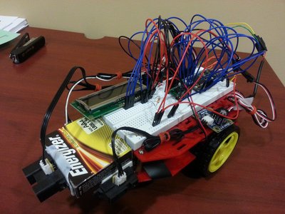
We have designed a simple robot which detects obstacles and correspondingly changes its direction to avoid collisions. We have used the mbed controller and interfaced it with an LCD display and 3 Infra-Red sensors. The LCD display indicates the distance of the robot from the obstacle when the robot is in the range of 80 cm to 10 cm and it also displays the direction in which the robot will turn when it sees an obstacle. The 3 infra-red sensors are used to detect obstacles in the front, right and left direction. The front sensor is the primary sensor which keeps checking if there are any obstacles in its path in the front direction. Simultaneously the right and left sensors also keep checking for obstacles in the right and left direction respectively. Whenever there is any obstacle detected in the range of 10 centimeters by the front sensor, the robot will stop and take a turn in either the right or left direction depending on which side is clear and free from obstacles. If both the right and left side are free from obstacles, we have made the robot turn right (One could make it turn left by choice). When the front sensor and left sensor both detect obstacles within the range of 10 centimeters, the robot is made to turn right. Similar logic is used to make the robot left turn. If all the 3 sensors detect obstacles within the range of 10 centimeters, the robot moves in the reverse direction.

Equipment
- Mbed NXP LPC1768
- Magician Chassis Robot
- Sharp IR sensor GP2Y0A21YK0F
- Dual H-Bridge md08a
- 16x2 LCD Text Display HD44780
Images

Demo
Connections
| MBED | Dual H-Bridge Breakout | Robot DC Motors | Battery |
|---|---|---|---|
| Vin | Vmot | + | |
| GND | GND | - | |
| Vout | Vcc | ||
| p21 | PWMB | ||
| P22 | BIN2 | ||
| p23 | BIN1 | ||
| p24 | AIN1 | ||
| p25 | AIN2 | ||
| p26 | PWMA | ||
| Vout | /STBY | ||
| A01 | LEFT RED | ||
| A02 | LEFT BLACK | ||
| B02 | RIGHT BLACK | ||
| B01 | RIGHT RED |
| MBED | LCD Text Display |
|---|---|
| GND | GND |
| 5V | Vcc |
| GND Via 1K Resistor | VO |
| p15 | RS |
| GND | RW |
| p16 | E |
| N/C | D0 |
| N/C | D1 |
| N/C | D2 |
| N/C | D3 |
| p17 | D4 |
| p11 | D5 |
| p12 | D6 |
| p13 | D7 |
| MBED | IR-LEFT | IR-CENTRE | IR-RIGHT |
|---|---|---|---|
| VOUT | VCC | VCC | VCC |
| GND | GND | GND | GND |
| p20 | CONTROL | ||
| p18 | CONTROL | ||
| p19 | CONTROL |
#include "mbed.h"
#include "motordriver.h"
#include "TextLCD.h"
 DigitalOut myled(LED1);
 AnalogIn ain1(p20);
 AnalogIn ain2(p18);
 AnalogIn ain3(p19);
 TextLCD lcd(p15, p16, p17, p11, p12, p13); // rs, e, d4-d7


Motor left(p21, p22, p23, 1); // pwm, fwd, rev, has brake feature
Motor right(p26, p25, p24, 1);

int main() {

   float temp,temp2,temp3;
   while (1) {
   temp=100*(1- ain1);
   if(temp>40){
   lcd.printf("distance=%f",temp);
   left.speed(0.4);
   right.speed(0.4);
   wait(0.5);
   left.stop(0.5);
   right.stop(0.5);
   wait(0.005);
   temp2=100*(1- ain2);
   temp3=100*(1- ain3);
   if(temp2<40){
   lcd.printf("Take right turn");
   left.speed(0.4);
   right.stop(1);
   wait(0.1);
   left.stop(1);
   right.stop(1);
   wait(0.1);
    }
   if(temp3<40)
   {
   lcd.printf("Take left turn");
   left.stop(1);
   right.speed(0.4);
   wait(0.1);
   left.stop(1);
   right.stop(1);
   wait(0.1);
    }
   if(temp2<40 && temp3<40){
   float s;
   s=(-1)*(0.5);
   lcd.printf("Take reverse turn");
   left.speed(s);
   right.speed(s);
   wait(2);
   left.stop(1);
   right.stop(1);
   wait(0.5);
    }
   lcd.cls();
}
else
{
   temp2=100*(1- ain2);
   temp3=100*(1- ain3);

   if(temp2<40 && temp3>=40){
   lcd.printf("Take right turn");
   left.speed(0.4);
   right.stop(1);
   wait(0.6);
   left.stop(1);
   right.stop(1);
   wait(0.5);
    }

   if(temp2>=40 && temp3 <40){
   lcd.printf("Take left turn");
   left.stop(1);
   right.speed(0.4);
   wait(0.6);
   left.stop(1);
   right.stop(1);
   wait(0.5);
    }
   if(temp2 >40 && temp3 >40){
   lcd.printf("Take right turn by default");
   left.speed(0.4);
   right.stop(1);
   wait(0.6);
   left.stop(1);
   right.stop(1);
   wait(0.5);
    }
   }
  }
}
Problems Encountered and Possible Solutions
The robot turns approximately by 90 degrees since we have used the wait function to make it turn. It could be made to turn to exact 90 degrees by using a compass module. But the problem is that the robot DC motors have magnets. The magnetic field of these magnets interfere with the field of the compass and hence the compass gives stray values.
One can try to eliminate this problem by placing the compass as far as possible by placing the compass on a pole of a reasonably large height. The compass needs to be at a minimum distance of greater than 5 inches to work properly. Also one needs to take care of the magnetic fields of the surroundings in order to make the compass work properly.