Joystick as USB Mouse
Import programUSBAbsoluteMouse
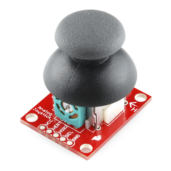
Uses a Sparkfun Thumb Joystick to control the X and Y coordinate returned from the mbed device acting as a HID based absolute mouse.
Last commit 07 Dec 2011 by  Adam Green
Overview
This demo uses a Sparkfun Thumb Joystick to control the mouse cursor on a PC. The joystick is interfaced to the PC through the use of a mbed-m0 device. The mbed device is running firmware which takes advantage of the USBMouse C++ class provided by the latest mbed libraries.
When first playing around with my mbed-m0 device, I tried out several of the USB samples provided in the mbed handbook. One of samples moved the mouse cursor around in a circular motion at the center of the screen using absolute rather than relative coordinates. A simple next step was to remove the trigonometric functions used to programmatically place the cursor and instead connect two 10k potentiometers that were readily available on the development board in which I had placed the mbed-m0 device. As Simon described my hack, it kind of worked like an Etch-A-Sketch controlling a mouse cursor. These potentiometers had just over 180 degrees of rotation and actually worked quite well at locating the cursor on the screen. I then thought it would be fun instead to use a thumb joystick like that found on the controllers used by video game consoles. It turns out that Sparkfun has just the thing available here, including a breadboard friendly breakout board. The potentiometer on each axis of this controller can rotate about 90 degrees.
Reasons that the thumb joystick doesn't make a good pointing device:
- The limited 90 degrees of rotation makes it very difficult to accurately place the cursor on the screen. A small amount of movement on the joystick results in a large motion on the screen. This wasn't as much of an issue with the potentiometers that had over 180 degrees of rotation.
- The self-centering feature of these joysticks force the user to keep more pressure on the stick when attempting to place the cursor so that it doesn't rotate back to the center position. Towards the end of this page, I discuss a modification I made to remove this self-centering functionality.
- The potentiometers in the joystick appear to have a built-in dead zone. You can move the joystick around the center location and see no change in the analog values from the potentiometers until you cross a particular threshold.
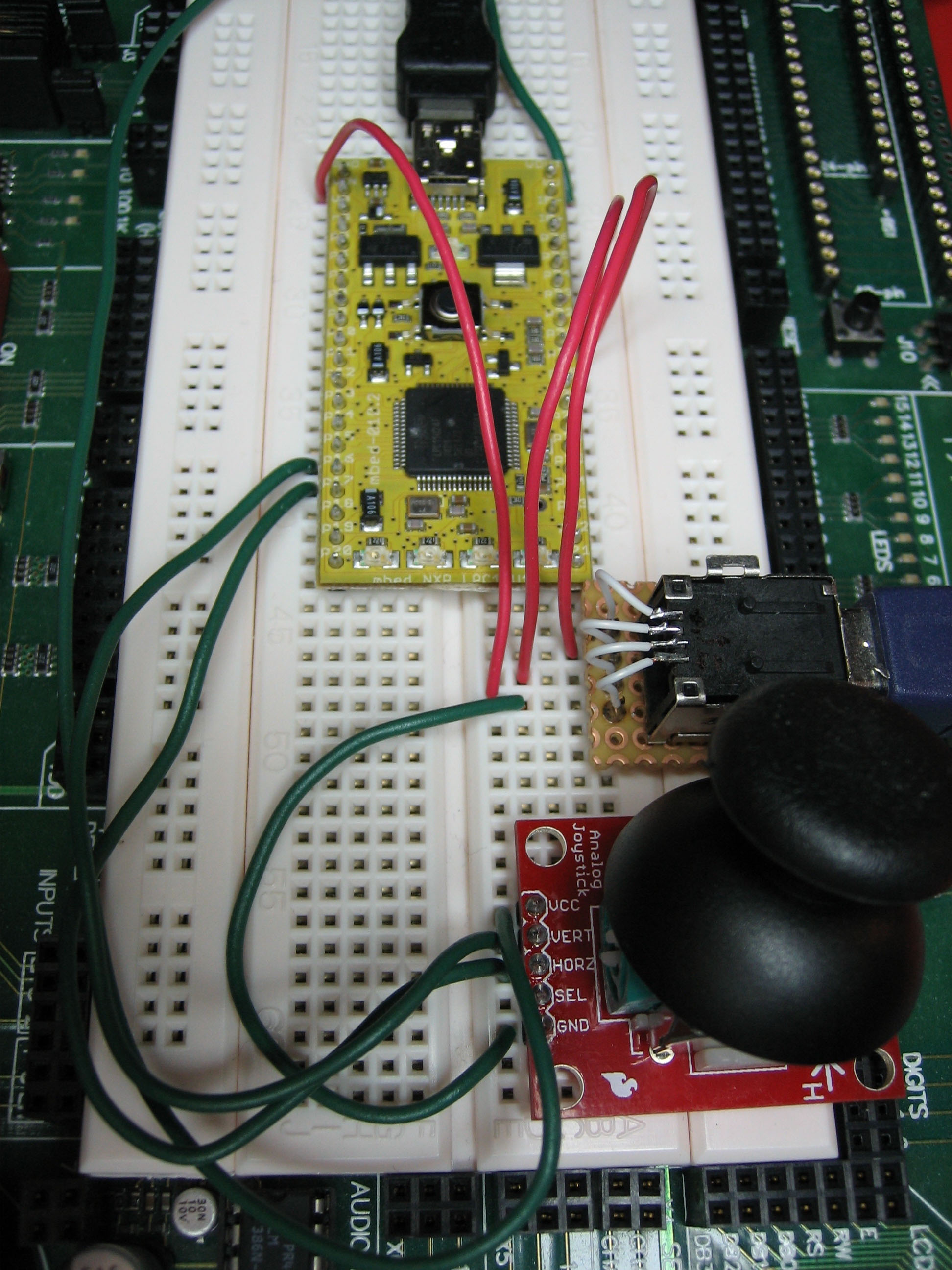
Wiring
Sparkfun Thumb Joystick Breakout
| Joystick Breakout | mbed |
|---|---|
| VCC | pin 40 - VOUT |
| VERT | pin 15 - p15 |
| HORZ | pin 16 - p16 |
| SEL | Not Connected |
| GND | pin 1 - GND |
Information
You could also connect the SEL pin to the mbed device and use a DigitalIn object with the mode set to PullUp and detect the pin going LO when pressed. I didn't however write the sample to send mouse button presses to the PC since the button on my joystick doesn't work very well after the removal of the spring loaded self-centering mechanism.
USB Breakout

Romilly Cocking has a notebook page which shows how to connect a Sparkfun USB breakout board to the mbed.
Warning
You don't need to connect the VCC pin of this breakout board if you are going to get power from the other USB cable over which the device is programmed.
Running Demo
- Connect a USB cable to the mbed as usual so that it can be programmed.
- Import my USBAbsoluteMouse sample code into your mbed compiler workspace.
- Build the sample for the LPC11U24 target type.
- Deploy resulting binary to your mbed-m0 as usual.
- Connect another USB cable between the USB breakout board discussed above and your PC.
- Press the reset button on the mbed device.
- The mbed device should be enumerated by the PC as a HID mouse.
- Moving the joystick around should cause the mouse cursor to move on the screen.
Removal of Self-Centering Mechanism from Joystick
To remove the self-centering mechanism on the joystick, I flipped it upside and drilled a 13/32" hole in the bottom of the joystick. This allowed the spring loaded centering mechanism to drop out of the device.
The following two pictures show what the device looks like from the bottom before and after the hole was drilled.


Once this modification had been made, I soldered the device to the breakout board.
1 comment on Joystick as USB Mouse:

Please log in to post comments.
.