Important changes to forums and questions
All forums and questions are now archived. To start a new conversation or read the latest updates go to forums.mbed.com.
4 years, 12 months ago.
L433RC-P with an external power supply 3.3V
Hello
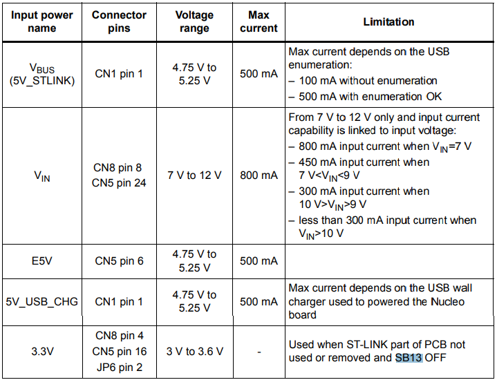
I'm supplying the Nucleo Board L433RC-P with 3.3V external voltage. For that I connected to CN5 pin 16 an external voltage of 3.3V and I desoldering SB13 as the datasheet said.
I have connected to the microcontroller a LCD that communicate with the microcontroller by SPI, and one digital out connected to one LED. When I supply the microcontroller with the 3.3V, this voltage arrive correctely to it, but the microcontroller doesn´t run the program, because it doesn´t send the SPI commands and the digital out commands. However if I keep the same configuration and connected the ST-LINK USB, the microcontroller start to work. Why happens this? If the microcontroller is supply externally it should be work without be connected to the ST-LINK USB.
Thanks in advance.
2 Answers
4 years, 12 months ago.
The nucleo board has two processors: One manages the USB for drag-and-drop, JTAG, serial and it *also* supplies the clock for the main processor. The problem is you supplied power to the main processor only. You need to follow the manual about supplying the USB processor with power as well. That is why it works only with USB connected. Look in the manual for "3V3_ST_LINK" and you should be able to find how to make this work. Hint: You will need a second connection and more SB mods...
4 years, 12 months ago.
Looking at the RM, this board does not show MCO (swd clock) SB64 as being used, I would check this first. If it is fitted then not running the SWD MCU will cause a no clock situation.
But....
The 8MHz HSE Xtal is not shown as populated either. Check to see if this is fitted, if it is then this is normally the first line of attack when the MCU comes out of reset so in theory it should work.
If that's not fitted either then in most STM cases the last clock mode is IRC so that should also start as a last resort.
But....
Not all the STM clock set up's are the same so you will need to check the system clock file for your particular board in the Mbed library. Also check the Target.json file for target overrides, sometimes the IRC set up is not enabled for that Target.
I would suggest to run a basic 'Blinky' program to confirm that the MCU is actually starting. If it does then problem is not clocking.

Hi there, I do not have this board but can by similar like another one. Also some more information about your project will help.
That can by only a power supply problem.
Best regards J.
posted by Jan Kamidra 29 Apr 2019