Important changes to forums and questions
All forums and questions are now archived. To start a new conversation or read the latest updates go to forums.mbed.com.
5 years, 2 months ago.
ADC LTC1859 skipping values/jumpy output
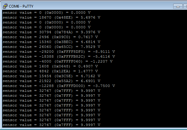
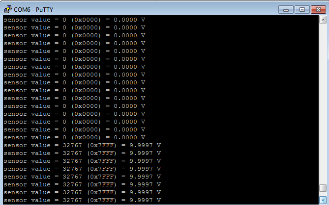
Morning all, I previously posted about help with a F303RE using SPI and an external ADC; Andy helped me a lot! It is here for reference: https://os.mbed.com/questions/84596/SPI-external-16-bit-ADC/#answer16061 Over the past few days I have been trying to make the output cleaner. With a sine wave applied the output is very "jumpy" as can be seen in the first attachment. The second one shows the output for a square wave which is obviously better, though for some reason it doesn't show -10V.
What I'm confused about is the datasheet states that the LTC1859 has a sampling rate of 100ksps which seems great. I thought maybe the sample and hold could be the problem, but it doesn't seem there is anywhere to change that in the datasheet (https://www.analog.com/media/en/technical-documentation/data-sheets/185789fb.pdf)
I am feeding a slow sine wave, 0.3Hz! So I should be seeing a smooth output from -/+10V -> this is the WORD I have LTC configured to as input.
I have double checked my 'waits' so that they comply with minimum conversion time. I also made my hardware cleaner to eliminate a noise problem.
It seems to be better when I have the SPI mode changed from 0 to 1, but I can't tell from the data sheet if CPHA should be 0 or 1.
Attached is my code:
LTC_ADC
#include "mbed.h"
 // transfers are 16 bits with the config as the first 8
#define _configWord_ 0x0400 // Read channel 0, single ended, 0-5V range, don't power down.

 // NUCLEO F303RE, using CN10 SPI1_SCLK=11=PA5, SPI1_MISO=13=PA6,
 // SPI1_MOSI=15=PA7
SPI spi(PB_15, PB_14, PB_13); // mosi(out), miso(in), sclk(clock)

DigitalOut rd(PA_12); // cs (the chip select signal)

Serial pc(USBTX, USBRX); // tx, rx ( the usb serial communication )

int main() {
    rd = 1;
    wait_us(100);
    spi.format(16,1);

    // ours has max 20MHz for sck so I guess 1Mhz is okay
    spi.frequency(1000000);

    // notify the user that we are starting with the ADC communication
    pc.printf("Starting ADC interaction\n");

    rd = 0;
    // t9, once bring RD low, there is min time delay for the SCK setup time of 20ns

    // only really needs to be 20 ns which probably means we don't need the wait
    // at all
    wait_us(10);

    // write word for the setup we want
    spi.write(_configWord_ );

    // t13, the time delay after the word is finished being acquired to RD high
    // only really needs to be a few ns which probably means we don't need
    // the wait at all
    // think it is t13, changed from micro to nano

    // might be too less, poster said wait_us(10)
    wait_us(10);
    rd = 1;

    // lets do this for 200 values
    int i=1;
    while (i<=200) {

        // Same as above
        rd = 0;
        wait_us(10);

        // signed 16 bit integer
        int16_t receiveValue = spi.write(_configWord_ );
        wait_us(10);
        rd = 1;

        // print it for the user
        // When trying to figure out what's going on with binary data printing
        // as hex is often more useful.

        // %i scan an integer as a decimal (signed int)
        // capitol X gives capitol letters for hex
        // # gives 0x in output so you know it is hex
        // % is the number
        // 04 is how many entries can be made
        // so if i=7 0x%04x, 0x0007
        // %f decimal floating point
        // last entry is the analog voltage read
        // have to change the value at the end for the reference voltage
        // it is 20 for +-10 because the peak-peak is 20

        pc.printf("sensor value = %i (0x%04X) = %.4f V\r\n", receiveValue,receiveValue, (20.0f*receiveValue)/65536);

        // delay some time before reading again

        // typical conversion time is 4us, max is 5us.
        // should be at least the conversion time. Conversion starts when
        // read goes high (unless controlled independently)
        wait_us(3);
        i=i+1;
    }
}
Sine Wave Output:

Square Wave Output:

Thank you all. This questions site is very helpful when you have looked everywhere and are out of ideas!
- Chris
1 Answer
5 years, 2 months ago.
I do not have an answer, but a couple suggestions.
1) I would start with a plain DC level first from -10V to +10V in say 0.5V steps. Record the input voltage from signal generator, the input voltage at the ADC (if there is any sort of scaling or buffering before hitting ADC) and record results seen in the micro. Make sure this simple case is working as expected before moving on to time-varying signal.
2) Hook up an oscilloscope and see if you have any noise on the ADC Vdd/Vref input or the ADC channel input. When the ADC samples the channel, it will load it slightly and you might see the voltage sag. You can probably trigger scope based on your rd signal. You should be able to adjust the ADC hold time before starting conversion if needed so you wait until the sag has recovered. Or make changes to circuit to reduce the voltage sag.
3) Use oscilloscope to measure actual sample interval. There can be a large amount of time jitter in your wait calls because the rtos may get involved with thread switching or going to sleep. If you’re trying to measure an AC signal this large uncertainty in timing will give as much or more error than the actual voltage level. Basically the way you are doing it now you have assumed the samples are at equal intervals, which is not true.
4) The 10us to 20us loop timing is quite demanding. Rtos task switching usually works on the order of 1 to 10 ms (100 to 1000 times longer). Clock here is 72MHz or 13.9ns tick. So you can only squeeze in maybe 700 instructions between each 10us window. Spinning in a tight loop might work if this is all you have to do.
5) Your innocent looking pc.printf statement is going to add significant time to the loop. Even at 115200 baud, that should be around 90us to print each character. You need to take this out to have any hope of hitting your timing. Consider doing some readings then printing result after. Even moving printf to another thread, timing will be tricky.
A Ticker can be used to Use a Ticker to run function at regular interval in ISR context. This may or may not provide more even sampling. It has to be tested. Documentation notes that sleep is disabled if Ticker is used to improve accuracy, which is a good sign. There's an example in the documentation:
https://os.mbed.com/docs/mbed-os/v5.11/apis/ticker.html#a9bd57da154ea4898f7b5ae0cb992d8db
It looks like wait_us() probably is spinning in a tight loop like you expect. If this is the only thing your program is doing it may be possible to get reasonable timing this way. You may want to disable the Rtos and disable Sleep, as these could mess up the timing of the main loop. These can probably be configured, I just don’t know how off the top of my head. Down side is you will struggle to do anything else in your program.
Handling transmit and receive in ISR could free up some cycles. It may also be possible to setup DMA transfers so this work can be offloaded from the CPU. I’ve not used DMA in mbed.
Graham, I will do the DC suggestion, then look into interrupts. What you said "Basically the way you are doing it now you have assumed the samples are at equal intervals, which is not true" makes complete sense.
I haven't worked with interrupts much, but found this link: https://os.mbed.com/users/tkreyche/notebook/ad7190-ultra-low-noise-24-bit-sigma-delta-adc/ which I think would be a good start.
Would you be able to recommend other references?
Thanks!
posted by 21 Feb 2019I modified my answer. Bottom line, is the timing here - 20us between samples - makes this challenging. You are running out of time for micro to do anything else between samples. And put a scope on the output pin, it will show you the actual timing you are getting.
posted by 21 Feb 2019Graham, I may be confused. I was looking at the data sheet and the reason my timing is so tight is because there are max values which I figured I wouldn't be able to go over. For example, the conversion time has a max value of 5 micro seconds. Perhaps I read it wrong, this is just telling me how long it 'could' take? The 10 micro seconds are because of a delay in bringing RD low and SCK; this is t9.
I read on the printf yesterday, I have since moved it after the conversion time so it was at the end of the conversion.
I appreciate the references and will do heavy research and debugging today as per your suggestions.
posted by 21 Feb 2019