Important changes to forums and questions
All forums and questions are now archived. To start a new conversation or read the latest updates go to forums.mbed.com.
5 years, 7 months ago.
CAN example on LP1768
Hi,
I'm trying to get the CAN example (https://os.mbed.com/handbook/CAN) to work on my setup with the LP1768.
Here is the code I'm using
#include "mbed.h"

Ticker ticker;
DigitalOut led1(LED1);
DigitalOut led2(LED2);
CAN can1(p9, p10);
CAN can2(p30, p29);
char counter = 0;

void send() {
    printf("send()\n");
    if(can1.write(CANMessage(1337, &counter, 1))) {
        printf("wloop()\n");
        counter++;
        printf("Message sent: %d\n", counter);
    }
    led1 = !led1;
}

int main() {
    printf("main()\n");
    //ticker.attach(&send, 1);
    CANMessage msg;
    while(1) {
        send();
        //wait(0.1);
        //printf("loop()\n");
        if(can2.read(msg)) {
            printf("Message received: %d\n", msg.data[0]);
            led2 = !led2;
        }
        wait(1);
    }
}
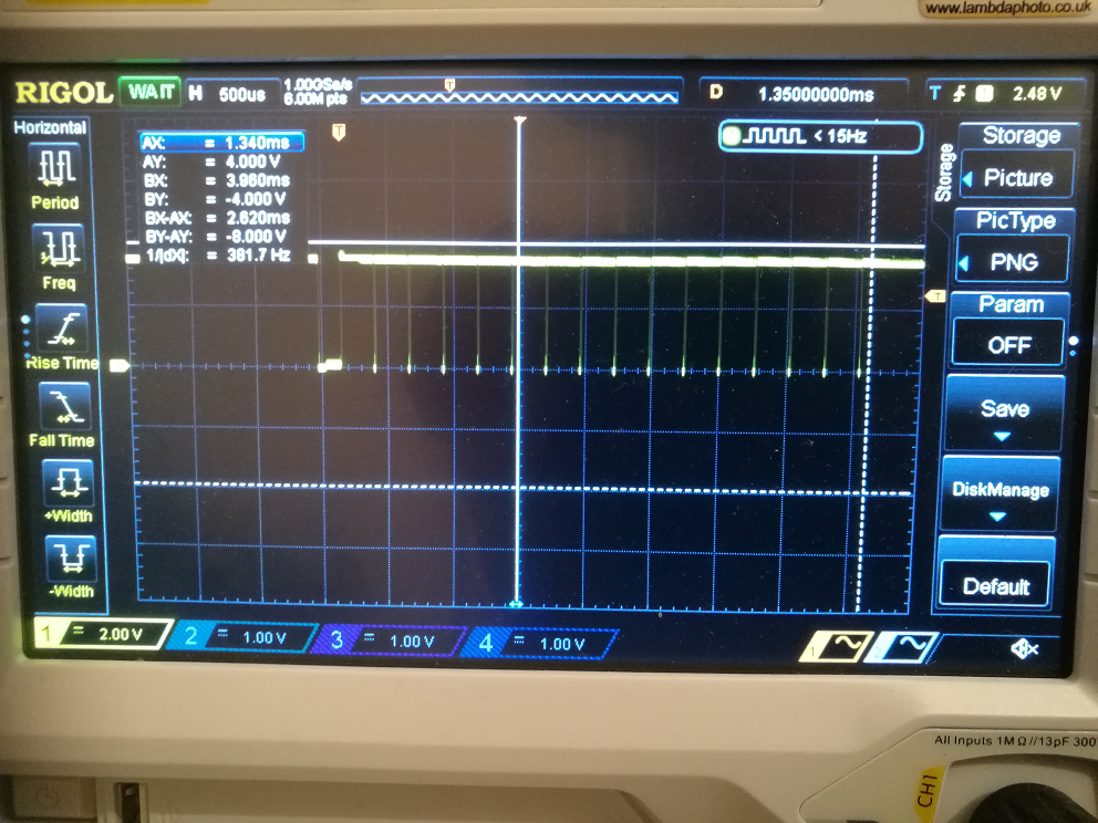
The bus is terminated both ends with 120 ohm. On the RX pin (p30) on can 2 (so the recieve CAN) I am getting the following scope trace:

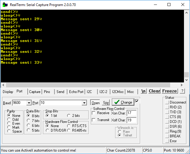
But on my serial termianl the mbed does not appear to recieve anything:

I have a few questions:
- What am I doing wrong?
- What is the default CAN frequency?
- Is it normal to see the TX signal on CAN 1 also mirrored on CAN 1's RX pin?
- In the scope trace the message does not appear to have a counter in, as in the message stays constant in the scope trace even though the send message is being passed an incremental counter, why?
Many thanks for any help,
Joe
********additional info below ********
I have change the code to be the same as the example:
#include "mbed.h"

Ticker ticker;
DigitalOut led1(LED1);
DigitalOut led2(LED2);
CAN can1(p9, p10);
CAN can2(p30, p29);
char counter = 0;

void send() {
    printf("send()\n");
    if(can1.write(CANMessage(1337, &counter, 1))) {
        printf("wloop()\n");
        counter++;
        printf("Message sent: %d\n", counter);
    }
    led1 = !led1;
}

int main() {
    printf("main()\n");
    ticker.attach(&send, 1);
    CANMessage msg;
    while(1) {
        printf("loop()\n");
        if(can2.read(msg)) {
            printf("Message received: %d\n", msg.data[0]);
            led2 = !led2;
        }
        wait(0.2);
    }
}
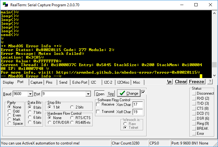
It compiles but when I flash this to the LP1768 the serial print out is this:

I also notice that in some of the API notes the CAN constructor is overloaded to accept the bus frequency as an input, but this does not work.
the firmware version for the LP1768 I'm using is 141212.
Many Thanks,
Joe
2 Answers
5 years, 7 months ago.
Hello Joe,
- It seems that in your version the
readfunction is called too soon afterwrite. Try to revert back to the original code published in the handbook. - The default CAN frequency for LPC1768 boards is 100 000 Hz.
- Each CAN node reads it's own packet when transmitting it. So it's normal to have the TX signal also at RX pin.
- Since data represents only a fraction of a CAN packet it's hard to make a conclusion based on a scope trace.
Hi Zoltan, thanks for taking the time to look at my question, I've added info to the above.
posted by 30 Sep 2018It seems that you are using mbed-os5. In that case I would suggest to try the following code:
#include "mbed.h"

DigitalOut led1(LED1);
DigitalOut led2(LED2);
CAN can1(p9, p10);
CAN can2(p30, p29);
char counter = 0;

void send(void const *args) {
    while (true) {
        wait_ms(1000);
        printf("send()\n");
        if(can1.write(CANMessage(1337, &counter, 1))) {
            printf("wloop()\n");
            printf("Message sent: %d\n", counter);
            counter++;
        }
        led1 = !led1;
    }
}

int main() {
    Thread thread(send);

    printf("main()\n");
    CANMessage msg;
    while(1) {
        printf("loop()\n");
        if(can2.read(msg)) {
            printf("Message received: %d\n", msg.data[0]);
            led2 = !led2;
        }
        wait_ms(200);
    }
}
Hi Zoltan,
I've used the above and it sucessfully runs on the LP1768 now thank you. There is still no recieved message print out to serial.
When I look at the signal on pin 10 of the LP1768 (so the TX pin) the signal still looks like the one in the scope image above, I can confirm that on pin 30 (so the RX pin) I see thae same signal that was sent from the TX pin.
There does not appear to be a counter in this message as it never changes. When was this CAN library last checked to be working on the bench, is ther a way to verify its working?
Many Thanks,
Joe.
posted by 03 Oct 2018Hello Joe,
I had run the program on my mbed LPC1768 board with the latest mbed-os 5.10.0 and it worked reliably. So I'd suggest to double check the wiring. Maybe the CAN-H / CAN-L lines are swapped on one of the MCP2551 chips. If after a transmission there is no acknowlege signal generated by a receiver then the transmitter automatically repeats the same transmission again and again. In that case the payload data will not change but the interval between the CAN packets will be shorter than 1 second.
posted by 03 Oct 20185 years, 6 months ago.
hi Joe,
It's a bit hard to tell from the scope trace, but it looks like a stream of "stuff-bits" and not data. I would suggest you verify that you have wired it correctly to the schematic on the handbook page. I don't think you'll find the solution on my CAN page, but perhaps it will fill in a bit of information to help you solve this.
Since you have a 4-channel scope, perhaps you could capture the tx, rx, CAN-H and CAN-L signals for another scope trace. This may help us see what is happening.
David, thanks for the reply its appreciated, I will do a full scope trace once the example compiles and runs on my lp1768 (i've added info above)
posted by 30 Sep 2018Something else that comes to mind - what version of the OS are you using?
In theory, we'd like to expect that it doesn't matter, but perhaps it is somehow related to that. The early examples of CAN were based on MBED OS v2, and even early releases - well before v121. I did quite a bit of CAN work with v2, and actually none with v5, so I can't attest to any potential differences there.
posted by 30 Sep 2018