Important changes to forums and questions
All forums and questions are now archived. To start a new conversation or read the latest updates go to forums.mbed.com.
7 years, 1 month ago.
Nucleo-L053R8 Serial 2 is not working but serial 1 is working

Hello,
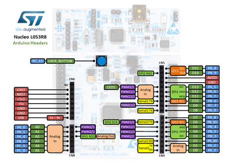
I am using Nucleo-L053R8 for my project. I have connected external FTDI pins ti serial 1 i.e. D8 and D2 pins and its working fine. When I connect FTDI to Serial2 i.e. D1 and D0 its not working. I see that D1 and D0 pins also used for Analog In pins. What is the reason for not working??. Thank you.
1 Answer
7 years, 1 month ago.
Hello Mohan,
Pins D0 and D1 are used for the serial connection with your PC over STLink. See the warning "Shared UART on pins D0 and D1" just below the Nucleo pinout on Arduino-compatible headers at this link. For information on how to enable them for other functions have a look at:
https://developer.mbed.org/teams/ST/wiki/Use-of-D0D1-Arduino-pins
 Thank you Mr.Zoltan.
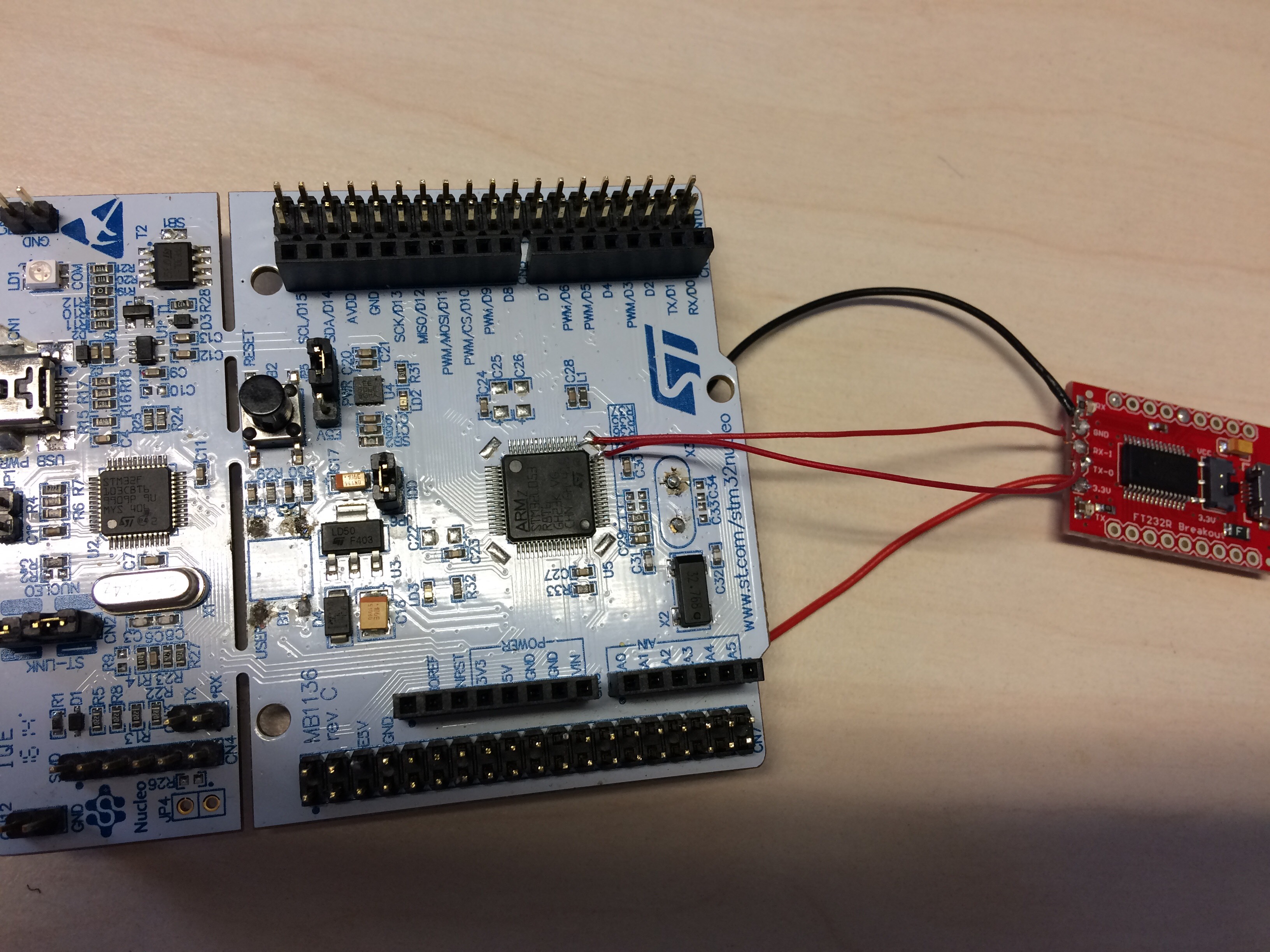
I have used D0 and D1 pins for my custom board. I gave Do and D1 pins to the FTDI. I have connected D0 (PA_3) and D1 (PA_2) pins to TX-0 and RX-1 of FTDI respectively. Unfortunately I dont see the data.
When I connect the scope at PA_3 of contoller then I see the data on scope.
What is the reason??. Should I make extra hardware connections ??. Thank you again
posted by 09 Mar 2017Hello Mohan,
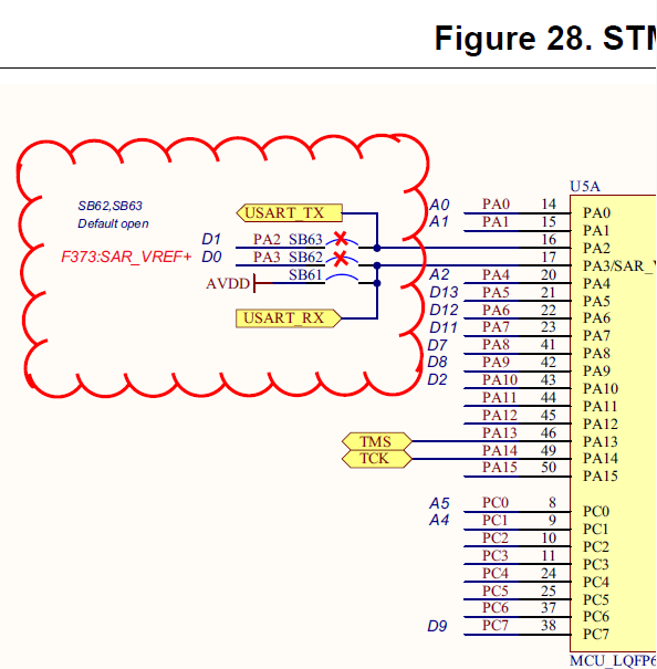
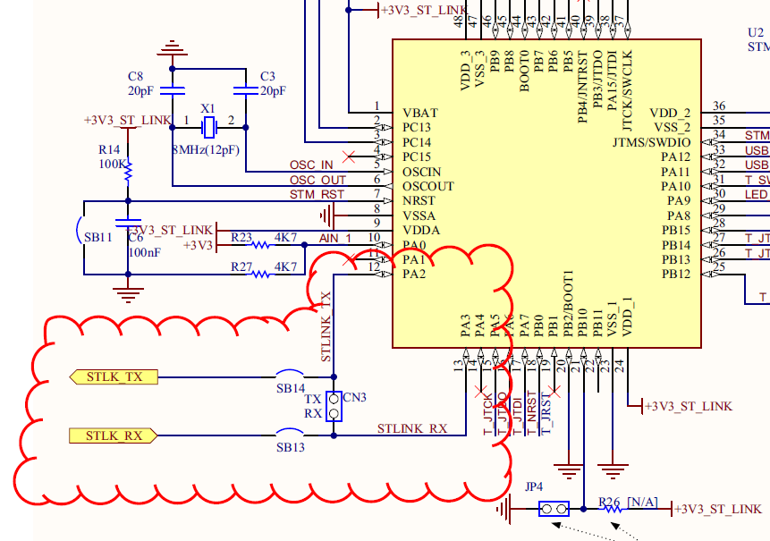
On pages 64 and 65 of the User Manual you'll find Electrical Schematics.


As you can see, solder bridges SB62 and SB63 are open by default - i.e. NUCLEO chip's PA2 and PA3 pins are not connected to the Arduino-compatible header's D1 and D0 pins. However, they are connected (over SB13 and SB14) to PA2 and PA3 pins of the ST-Link/V2-1 microcontroller which is actually an STM32F103CBT6 chip (see in figure 29) running as "Serial to USB" converter (similar to your external FTDI device). So once you solder an FTDI converter directly to the PA2 and PA3 pins of your NUCLEO board then you will end up with three chips connected to the same serial bus (NUCLEO chip, ST-Link chip and FTDI chip). That could explain why you don't receive any data over the FTDI (and most likely also over the STLink connection) but you can see some pulses on the scope. To make the the FTDI work, try to open (disconnect) the solder bridges SB13 and SB14 (located on the back side of your NUCLEO board). Moreover, if you then close (connect) also the solder bridges SB62 and SB63 then you do not have to solder your FTDI converter directly to the NUCLEO chip but rather you can connect it to pins D0 and D1. Please notice that once you open the solder bridges SB13 and SB14 i.e. disconnect the ST-Link microcontroller from the NUCLEO chip, your PC will stop to receive serial data over the ST-Link USB connection.
posted by 09 Mar 2017