Important changes to forums and questions
All forums and questions are now archived. To start a new conversation or read the latest updates go to forums.mbed.com.
7 years, 8 months ago.
I2C Stm32f4 , can not read the data
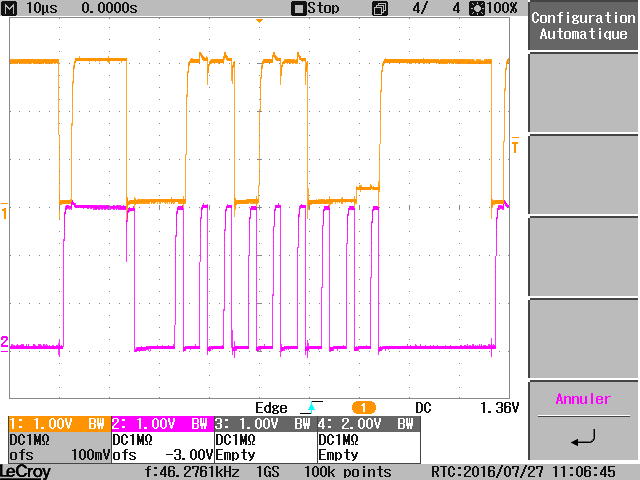
hello everybody, I'm having a problem with reading data from a maximGauge via I2C stm32f4. I used the oscilloscope to check the variations of SDA and SCL. Here the results. As u can see, I have the start signal, the sending address and also an ACK from the gauge. If i understood well, the connections is right while we are having the ACK. Now the data i need to receive is not really sent..
Here the code :
- include "stm32f4xx.h"
- include "stm32f4xx_gpio.h"
- include "stm32f4xx_rcc.h"
- include "stm32f4xx_i2c.h"
- define SLAVE_ADDRESS 0x6C the slave address
- define TIME_OUT 0xA time out constant
- define I2Cxx I2C1
void I2C1_init(void) {
GPIO_InitTypeDef GPIO_InitStruct; GPIO_InitTypeDef GPIO_InitStruct2; I2C_InitTypeDef I2C_InitStruct;
enable APB1 peripheral clock for I2C1 RCC_APB1PeriphClockCmd(RCC_APB1Periph_I2C1, ENABLE); enable clock for SCL and SDA pins RCC_AHB1PeriphClockCmd(RCC_AHB1Periph_GPIOB, ENABLE); enable clock for leds RCC_AHB1PeriphClockCmd(RCC_AHB1Periph_GPIOD, ENABLE);
LED configuration GPIOA GPIO_InitStruct2.GPIO_Pin = GPIO_Pin_1; GPIO_InitStruct2.GPIO_Mode = GPIO_Mode_OUT; set pins to OUT mode GPIO_InitStruct2.GPIO_Speed = GPIO_Speed_50MHz; set GPIO speed GPIO_InitStruct2.GPIO_OType = GPIO_OType_PP; pushpull mode GPIO_InitStruct2.GPIO_PuPd = GPIO_PuPd_UP; enable pull up resistors GPIO_Init(GPIOD, &GPIO_InitStruct2); init GPIOB
SCL and SDA configuration GPIOB
GPIO_InitStruct.GPIO_Pin = GPIO_Pin_6 | GPIO_Pin_7; PB6 for SCL and PB7 for SDA
GPIO_InitStruct.GPIO_Mode = GPIO_Mode_AF; set pins to alternate function
GPIO_InitStruct.GPIO_Speed = GPIO_Speed_50MHz; set GPIO speed
GPIO_InitStruct.GPIO_OType = GPIO_OType_OD; set output to open drain > the line has to be only pulled low, not driven high
GPIO_InitStruct.GPIO_PuPd = GPIO_PuPd_UP; enable pull up resistors
GPIO_Init(GPIOB, &GPIO_InitStruct); init GPIOB
Connect I2C1 pins to AF GPIO_PinAFConfig(GPIOB, GPIO_PinSource6, GPIO_AF_I2C1); SCL GPIO_PinAFConfig(GPIOB, GPIO_PinSource7, GPIO_AF_I2C1); SDA
configure I2C1
I2C_InitStruct.I2C_ClockSpeed = 200000; 100kHz
I2C_InitStruct.I2C_Mode = I2C_Mode_I2C; I2C mode
I2C_InitStruct.I2C_DutyCycle = I2C_DutyCycle_2; 50% duty cycle > standard
I2C_InitStruct.I2C_OwnAddress1 = 0x00; own address, not relevant in master mode
I2C_InitStruct.I2C_Ack = I2C_Ack_Disable ; disable acknowledge when reading (à changer par la suite)
I2C_InitStruct.I2C_AcknowledgedAddress = I2C_AcknowledgedAddress_7bit; set address length to 7 bit addresses
I2C_Init(I2C1, &I2C_InitStruct); init I2C1
GPIO_ResetBits(GPIOD, GPIO_Pin_1);
GPIO_SetBits(GPIOD, GPIO_Pin_1);
enable I2C1 I2C_Cmd(I2C1, ENABLE); }
Then the function Read:
void I2C_Read(uint8_t address, uint8_t command, uint8_t *data[2] ) {
uint32_t time_out; time out variable ErrorStatus status = SUCCESS; the status of progress static volatile ErrorStatus end = SUCCESS;
0# Wait until I2C1 is not busy any more Check flag BUSY = 0
time_out = TIME_OUT;
while (time_out != 0)
{
if (I2C_GetFlagStatus(I2Cxx, I2C_FLAG_BUSY) == 1)
{
time_out--;
if (time_out == 0)
{
status = ERROR;
}
}
else time_out = 0;
}
if (status != ERROR) { I2C_GenerateSTART(I2Cxx, ENABLE);
2# Wait for I2C1 EV5(BUSY,MSL,SB)> Slave has acknowledged start condition START correct
// After sending the START condition (I2C_GenerateSTART() function) the master has to wait for this event. It means that the Start condition has been correctly
// released on the I2C bus (the bus is free, no other devices is communicating).
time_out = TIME_OUT;
while (time_out != 0)
{
if (I2C_CheckEvent(I2Cxx, I2C_EVENT_MASTER_MODE_SELECT) == 0)
{
time_out--;
if (time_out == 0)
{
status = ERROR;
}
}
else time_out = 0;
}
}
if (status != ERROR) { uint32_t ev; uint32_t tab[TIME_OUT]; int i=0;
3# Send slave Address for write I2C_Send7bitAddress(I2Cxx, address, I2C_Direction_Transmitter); I2C_SendData(I2Cxx, (address << 1) | 0); check if slave acknowledged his address within timeout
time_out = TIME_OUT; while (time_out != 0) { I2C_CheckEvent(I2Cxx,I2C_EVENT_MASTER_TRANSMITTER_MODE_SELECTED) == 0) ev=I2C_GetLastEvent(I2Cxx); tab[i++]=ev; if (ev!=I2C_EVENT_MASTER_TRANSMITTER_MODE_SELECTED) {
time_out;
if (time_out == 0)
{
status = ERROR;
}
}
else time_out = 0;
}
ev=0; }
if (status != ERROR) {
I2C_SendData(I2Cxx, command);
time_out = TIME_OUT;
while (time_out != 0)
{
6# Check BTF (Byte Transfer Finished)
if (I2C_GetFlagStatus(I2Cxx, I2C_FLAG_BTF) == RESET)
{
time_out;
if (time_out == 0)
{
status = ERROR;
}
}
else
time_out = 0;
}
}
if (status != ERROR)
{
I2C_GenerateSTART(I2Cxx, ENABLE);
time_out = TIME_OUT;
while (time_out != (uint32_t) 0)
{
8# Check EV5 (is start bit sent?)
if (I2C_CheckEvent(I2Cxx, I2C_EVENT_MASTER_MODE_SELECT) == 0)
{
time_out;
if (time_out == 0)
{
status = ERROR;
}
}
else
{
time_out = 0;
}
}
}
if (status != ERROR) {
9# Send slave address
I2C_Send7bitAddress(I2Cxx, address, I2C_Direction_Receiver); I2C_SendData(I2Cxx, (address << 1) | 1);
time_out = TIME_OUT;
while (time_out != 0)
{
10# Check ADDR flag
if (I2C_GetFlagStatus(I2Cxx, I2C_FLAG_ADDR) == RESET)
{
time_out;
if (time_out == 0)
{
status = ERROR;
}
}
else
{
time_out = 0;
}
}
}
if (status != ERROR) { data[0] = I2C_ReceiveData(I2Cxx); I2C_AcknowledgeConfig(I2Cxx, ENABLE); data[1] = I2C_ReceiveData(I2Cxx);
12# Clear ADDR register by reading SR1 then SR2 register (SR1 has already been read) (void) I2Cxx->SR2;
end = status;
}
9# Generate STOP to terminate the frame I2C_NACKPositionConfig(I2Cxx,I2C_NACKPosition_Current); I2C_GenerateSTOP(I2Cxx, ENABLE); }
Then, then main fonction. The idea is to give to the function a tab and it changes it and fill it with the right data, received from slave device. I put 2 resistor of pull up of 1.5k. I connected them to the pin D1 and i out it in HIGH level.
I think the problem i have is maybe a problem of registers or programming the tabs.
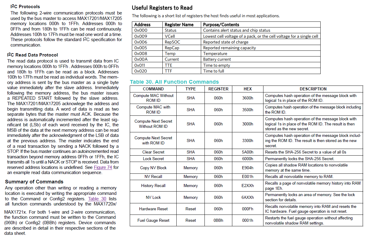
U ll find also documents of MAX17205, and screenshots from the oscilloscope. 
Thanks a lot for u help im a beginner, i will be really great-full if u can give me an advice.


1 Answer
7 years, 8 months ago.
Besides it is in general a ton of code, add <<code>> and <</code>> around it to make it readable. And in general, why aren't you using the mbed functions? Since we are on the mbed site and all ;).