Important changes to forums and questions
All forums and questions are now archived. To start a new conversation or read the latest updates go to forums.mbed.com.
8 years, 3 months ago.
Simple MBED led and switch set-up Help - LPC1768
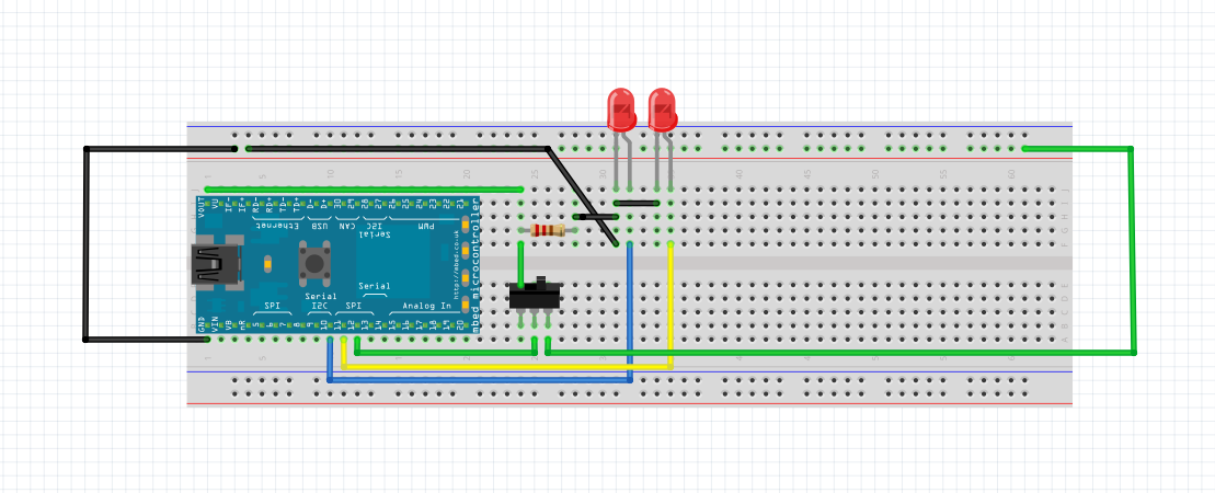
>>>Would this work with my program?:
So something like this?:

Does it matter that the right switch pin also links with the two LED's?
>>> ORIGINAL QUESTION:
Hello, i am new to MBED's and i am trying to follow a simple tutorial but i am having trouble understanding and copying the demonstration as i do not want to run the program and destroy any hardware by placing the resistor in the incorrect place.
Sorry if this is a dumb question but i am only 15 and i am interested in electronics but i do not want to destroy any of the hardware. Any help would be greatly appreciated.
Here is my program below which i am trying to build, but i am having trouble with the hardware:
Program 1
#include "mbed.h

DigitalOut LED1(p10);
DigitalOut LED2(p11);
DigitalIn Switch(p12);

int main() {

	while (1) {

		if (Switch == 0) {
			LED1 = 0;     // Turn led1 off.
			LED2 = 1;     // Turn led2 on
			wait(0.5);
			LED2 = 0;
			wait(0.5);
		}


		else if (Switch == 1) {
			LED2 = 0;
			LED1 = 1;
			wait(0.5);
			LED1 = 0;
			wait(0.5);
		}
	}
}
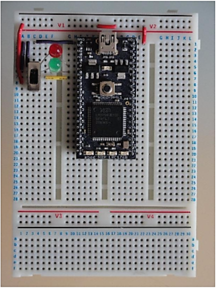
I am trying to replicate this diagram here but to the ports i specified in my program:

So for my program am i right in assuming:
The center of the switch is placed in p12 of the mbed.
Connect LED1's cathode to p10 and the anode to the current limit resistor - inline with 'G' on the breadboard
Connect LED2's cathode to p11 and the anode to the current limit resistor - inline with 'G' on the breadboard
Connect a wire directly from p12 to vout (Opposite side of breadboard (3.3v out))
Connect a wire directly from p11 to gnd (0v)
Connect a wire directly from p10 to gnd (0v)
Current a resistor to the same pin as both of the anodes of p11 and p12, and the otherside of the resistor as shown in the image. (E6)
2 Answers
8 years, 3 months ago.
)The center of the switch is placed in p12 of the mbed.
Fine, but you don't seem to mention the other switch connections. The fact that the switch has a "center" connection makes me think it is a "changeover" (SPDT) switch set up to either connect p12 to ground, or to connect p12 to VOUT (3.3v). That is sort-of OK, but have a look here: https://developer.mbed.org/users/4180_1/notebook/pushbuttons/ (for your current purposes you don't need to worry about debouncing).
)Connect LED1's cathode to p10 and the anode to the current limit resistor - inline with 'G' on the breadboard
)Connect LED2's cathode to p11 and the anode to the current limit resistor - inline with 'G' on the breadboard
Cool, but your photo shows no resistors. Probably, you would want to have one resistor for each LED, and the other end of each resistor (the end not connected to one of the LED anodes) would connect to VOUT (3.3V).
)Connect a wire directly from p12 to vout (Opposite side of breadboard (3.3v out))
No, that would keep the digital input always high ( = 1 ). Worse, depending on how you have connected the switch, you could end up shorting VOUT to ground.
)Connect a wire directly from p11 to gnd (0v)
)Connect a wire directly from p10 to gnd (0v)
No, that would keep the LEDs on all the time, and could do bad things when you try to drive p10 or p11 high - p10 and p11 should only go to the LEDs
)Current a resistor to the same pin as both of the anodes of p11 and p12, and the otherside of the resistor as shown in the image. (E6)
The resistors for the LEDs? See above.
8 years, 3 months ago.
I can't see any issues with Andy's answer above but just to make sure, you should have the following connections:
3.3V - 330 Ohm resistor - LED - P11
3.3V - 330 Ohm resistor - LED - P10

3.3V - Switch top
       Switch middle - (optional resistor) - P12
GND  - Switch bottom
When P10 or P11 are low current flows from 3.3V through the resistor, through the LED and into the mBed.
When the switch is up the top and middle are connected and P12 is connected to 3.3V, when the switch is down the bottom and middle are connected and P12 is connected to GND.
A little more detail:
How to work out how bright the LEDs are and the resistor values to use: LEDs (and all other diodes) are a little weird, they have an almost constant voltage drop, give them less voltage than that and they don't turn on, no current flows. Give them more voltage than that and they turn on and allow an almost unlimited amount of current to flow. Or at least they do until they overheat and go pop.
A typical LED drops about 1.6V (blue and white are normally about 3V but normal red/orange/yellow/green ones are all about that +/- 0.1V) and can normally take up to 20mA. Generally you want to aim for about 2 to 5mA, due to the way peoples eyes work anything more than that doesn't make them look much brighter and going much over 10mA could be bad for the mBed.
How do you set the current? Using a resistor and Ohms law. voltage = current * resistance. We have 3.3V across the resistor and LED combined. The LED will take 1.6V no matter the current which leaves 1.7V for the resistor. 1.7V = 5mA * resistor Resistor = 340 Ohms
As indicated above the exact current isn't too critical and so the value of the resistor isn't that important either. Anything from 200 Ohms to 1kOhms will work fine.
The optional resistor on P12 is purely for protection, if P12 was set to be an output the mBed would try to drive the pin to one voltage, the switch could be connecting the pin to a different voltage. Two things fighting like that results in large currents and potential to damage the parts. By putting a resistor in there we limit the current that can flow and so protect the mbed from damage. Again exact value isn't too important as long as you keep the currents to under 10mA you'll be fine no matter what (use ohms law to work out the minimum resistor value needed).
Other things to watch out for that can damage the mbed - Short circuiting 3.3V to GND will destroy the 3.3V output regulator. Fortunately on the LPC1768 this is a separate regulator from the one the CPU uses so the CPU will still work but the 3.3V output will be dead.
ESD - watch out for static, ideally keep yourself grounded in some way but that's not always practical at home. Two basic tactics to use to minimize the risk of ESD - when picking up the board always touch a ground connection first (the USB connector body is a good bet) and if passing the board to a different person ensure your hand touches theirs before the board does, that way any static goes through you not the board.
Comment on your update- NO NOT LIKE THAT
There are two issues with that new top picture. First, the big one: The black wire at the top that goes across and then diagonally down to the LED. - What is that for? It connects 3.3V and GND together through the resistor and it means that if the LED pins go high you turn the LED on without a current limiting resistor. Remove that and things should work.
The second issue is that you really should have one resistor for each LED. Using one will work but the brightnesses when they are both on are unpredictable.
If in doubt sketch out the circuit you want first and then check that it matches what you have put together. In this case the circuit you should be aiming for is something like this https://dl.dropboxusercontent.com/u/25986954/IMG_20160121_085909.jpg
posted by Andy A 21 Jan 2016