Important changes to forums and questions
All forums and questions are now archived. To start a new conversation or read the latest updates go to forums.mbed.com.
9 years, 3 months ago.
PIT vs TPM timer channels
Do the TPM timer channels corespond to the PIT timer channels? I'm asking this because I'm working with the TFC-Shield and 2 servos are hardware-coded (if that is a term :)) ) to specific TPM channels, and I would also want to use the wait() functions from the mbed API. From what I have seen, the wait() function uses PIT interrupts, which in turn use channels 0 to 1, which also corespond to the TPM channels (as numbers). Also, are timers from a type related to other types? Like if I change the frequency for one timer type like PIT, I might change the frequency for a LPTMR?
Question relating to:
1 Answer
9 years, 3 months ago.
The Freescale MCUs have PIT, TPM and LPTMR as timers, these are all completely different from each other, PIT 0 and 1 for the KL25Z is indeed used for the wait function, and this will not be affected by the TPM channels. The mbed API uses those for PwmOut also, so thats the only thing you need to watch out for.
Hi Erik,
I used TPM_Type structure to configure TPM0 has a counter (TPM_EXTCLK), initialized PTE29 (ALT4) using pin_function() but my code is not working. I cannot find any problem with pin mapping since I am only using a DigitalOut for the LED_RED (MKL25Z) ...
Can you tell me what am I missing? Have you got an example to configure TPM?
Thanks!
posted by 20 Mar 2015Happened to have the source code open, here is the PWM source code of mbed for Freescale PWM: http://developer.mbed.org/users/mbed_official/code/mbed-src/file/01cb89f68337/targets/hal/TARGET_Freescale/TARGET_KLXX/pwmout_api.c. But I can do very little with just knowing your code isn't working. With no information what you see that is going wrong and which code you use I cannot help.
posted by 20 Mar 2015Sorry Erik! I have checked the pwmout_api.c ...
Basically if I select the internal clock (CMOD=01) this code will blink the led. Unfortunately I cannot find what I am doing wrong for the external clock to feed the TPM. I have wrote directly to the addresses, a little bit more hard to read ...
Thanks
/media/uploads/jmc499/new__1.txt
posted by 21 Mar 2015That is indeed harder to read. What kind of input are you using on your external input?
posted by 21 Mar 2015Cleaned up the code ... Made two versions, one uses the TPM0 module with the internal clock, sets MOD to 30000 with a prescalar in order to see the Blue Led on the board blinking. This code is working. /media/uploads/jmc499/tpm0_internalclk.c
The second version just changes the clock source to external, selects the TPM_CLKIN0 and ties it up to PTE29 (ALT4). A "square wave" is generated in PTB8 and by connecting a wire from PTB8 to PTE29 the Blue Led _shoud_ toggle every 2 seconds or so. /media/uploads/jmc499/tpm0_externallclk.c
I am a bit stuck ... but I have never worked with Freescale before (neither ARM). Thanks in advance Erik.
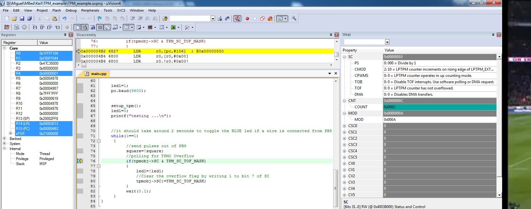
Edited ... Just moved the all project to Keil and debug it ... It is counting, but CNT (COUNT) goes above MOD and no overflow flag is generated ... please look at attached file.
I am indeed chasing a gosth for almost two weeks!!! Anyway I should have notice that I could export and debug in Keil.

Edited #2 Solved! :)
Just needed to clear the CNT register again. I have done that after calling the function in main(): tpmobj->CNT=0;
posted by 21 Mar 2015