Important changes to forums and questions
All forums and questions are now archived. To start a new conversation or read the latest updates go to forums.mbed.com.
9 years, 3 months ago.
I2C communication with MS5611, not getting the ACK bit
Hei,
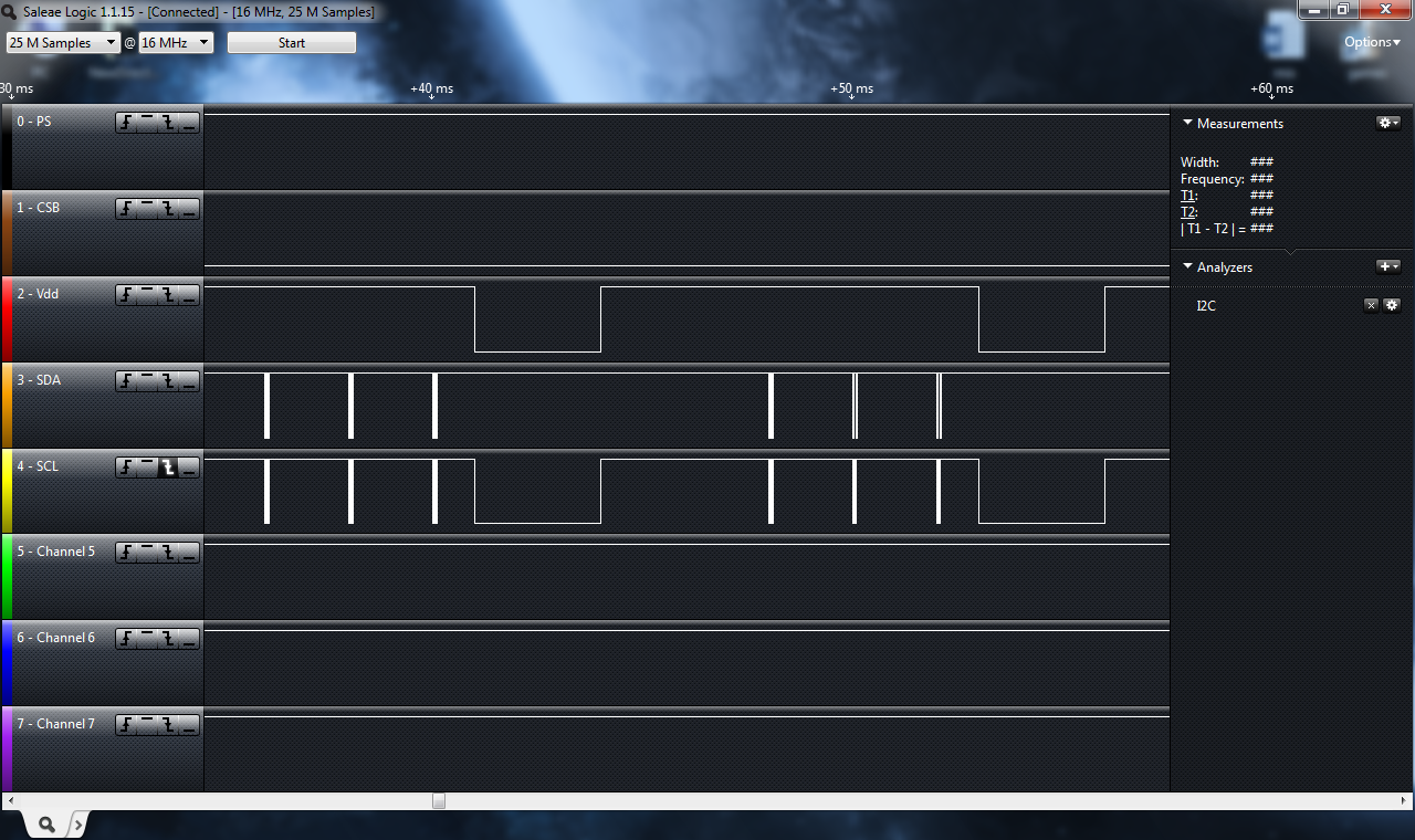
I am trying to communicate with the Barometric sensor MS5611, using the I2C protocol. My micro is STM32f3discovery. The address of the sensor is send, but not the command. I try to initialize the reset sequence, but the code is stucked in the while loop waiting for TXIS flag to be set. The purpose of TXIS flag is to indicate that all 9 bits are send. The reason why TXIS is not "one", is because the acknowledge bit from the MS5611 is not showing up. Also the I2C status register is setting the NACK (not acknowledge), STOPF (stop flag) bit.
The address of the MS5611 sensor is 11101110. This can be seen in the datasheet on the page 12. In my case the value of CSB is zero and PS (protocol select) is one.
Datasheet MS5611: http: //www.meas-spec.com/downloads/MS5611-01BA03.pdf
Also in the datasheet of MS5611 on the page 11 is stated that: “The reset can be sent at any time. In the event that there is not a successful power on reset this may be caused by the SDA being blocked by the module in the acknowledge state. The only way to get the MS5611-01BA to function is to send several SCLKs followed by a reset sequence or to repeat power on reset”
So, in the code I am sending 3x times the reset sequence and then I am resetting the sensor with GPIO pin and still not working. I tried with different CSB values, read write sequence, nothing.
What I am missing here ? thanks for the help
Here is my code:
void gpio_init(void)
{
  GPIO_InitTypeDef GPIO_InitStructure;

  /* Enable SCK and SDA GPIO clocks - they are both on port B*/
  RCC_AHBPeriphClockCmd(RCC_AHBPeriph_GPIOB  , ENABLE);

	/* I2C SCK  and SDA pin configuration */
	GPIO_InitStructure.GPIO_Pin = GPIO_Pin_6 | GPIO_Pin_7;
	GPIO_InitStructure.GPIO_Mode = GPIO_Mode_AF;
  GPIO_InitStructure.GPIO_PuPd  = GPIO_PuPd_NOPULL;
  GPIO_InitStructure.GPIO_OType = GPIO_OType_OD;
	GPIO_InitStructure.GPIO_Speed = GPIO_Speed_2MHz;
  GPIO_Init(GPIOB, &GPIO_InitStructure);

		/* VDD->Pin9 pin and PS->pin8*/
	GPIO_InitStructure.GPIO_Pin = GPIO_Pin_9 | GPIO_Pin_8;
  GPIO_InitStructure.GPIO_Mode = GPIO_Mode_OUT;
  GPIO_InitStructure.GPIO_OType = GPIO_OType_PP;
  GPIO_InitStructure.GPIO_PuPd = GPIO_PuPd_UP;
  GPIO_InitStructure.GPIO_Speed = GPIO_Speed_2MHz;
  GPIO_Init(GPIOB, &GPIO_InitStructure);

	GPIO_PinAFConfig(GPIOB, GPIO_PinSource6, GPIO_AF_4);  //SCK-> PB6
	GPIO_PinAFConfig(GPIOB, GPIO_PinSource7, GPIO_AF_4);  //SDA-> PB7

	GPIO_SetBits(GPIOB, GPIO_Pin_9);	//set PS (protocol select)-> enable I2C protocol
	GPIO_SetBits(GPIOB, GPIO_Pin_8);  // power up the sensor -> PB8->Vcc or Vdd
}

/*------------------------------------------------------------------------------------------------------*/

 void I2C_INIT(void)
{
  I2C_InitTypeDef  I2C_InitStructure;

  /* Enable the I2C periph */
  RCC_APB1PeriphClockCmd(RCC_APB1Periph_I2C1, ENABLE);

  /* I2C configuration */
  I2C_InitStructure.I2C_Mode = I2C_Mode_I2C;
  I2C_InitStructure.I2C_AnalogFilter = I2C_AnalogFilter_Enable;
  I2C_InitStructure.I2C_DigitalFilter = 0x00;
  I2C_InitStructure.I2C_Ack = I2C_Ack_Enable;
  I2C_InitStructure.I2C_AcknowledgedAddress = I2C_AcknowledgedAddress_7bit;
  I2C_InitStructure.I2C_Timing = 0x10420F13;  //0x00902025;  0x00310309

  /* Apply values to the I2C registers */
  I2C_Init(I2C1, &I2C_InitStructure);

  /*Start I2C Peripheral */
  I2C_Cmd(I2C1, ENABLE);
}

/*------------------------------------------------------------------------------------------------------*/

 void Alti_reset( uint8_t ComandAddr)
{
  /* Test on BUSY Flag */
  while(I2C_GetFlagStatus(I2C1, I2C_ISR_BUSY) != RESET){};

  /* Configure slave address, nbytes, reload, end mode and start or stop generation */
  I2C_TransferHandling(I2C1, ADDR_W, 1, I2C_AutoEnd_Mode, I2C_Generate_Start_Write); // I2C_Reload_Mode I2C_Generate_Start_Write, I2C_Reload_Mode
	//Delay(1);

	 x=0;

  /* Wait until TXIS flag is set */
    while(I2C_GetFlagStatus(I2C1, I2C_ISR_TXIS) == RESET )
	  {
			//I2C1->ICR = I2C_ICR_STOPCF;
			//I2C1->ICR = I2C_ICR_NACKCF;
			I2C_TransferHandling(I2C1, ADDR_W, 1, I2C_AutoEnd_Mode, I2C_Generate_Start_Write);
			Delay(1);    // delay in ms
			x++;

			  if (x == 3)  // reseting the sensor
			  {
			  GPIO_ResetBits(GPIOB, GPIO_Pin_9);	// get the VDD pin low
			  Delay(3); // delay in ms
			  GPIO_SetBits(GPIOB, GPIO_Pin_9); // 	get the VDD pin high
			  Delay(3); // delay in ms
				x = 0;
			  }

		  Delay(1);
	  }

  /* Send Register address */
  I2C_SendData(I2C1, (uint8_t) ComandAddr);

  /* Wait until STOPF flag is set */
  while(I2C_GetFlagStatus(I2C1, I2C_ISR_STOPF) == RESET);

  /* Clear STOPF flag */
  I2C_ClearFlag(I2C1, I2C_ICR_STOPCF);
}
Here are my waveforms:

