Important changes to forums and questions
All forums and questions are now archived. To start a new conversation or read the latest updates go to forums.mbed.com.
10 years, 6 months ago.
LPC1114FN28の7,8Pinの名称について
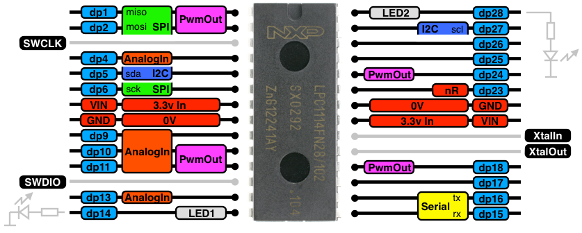
こちらhttp://mbed.org/platforms/LPC1114FN28/のページの"Pinout"の項にある図
 で、Pin7=VIN, Pin8=GND となっていますが、この端子はAD変換の基準電位を与えるための端子です。
この端子を電源に接続しないとAD変換結果が正常に出ません。
また、Pin21=VIN, Pin22=GNDがありますが、こちらがLPC1114FN28駆動用の電源の供給用の端子になります。
同じ"VIN","GND"の名称がつけられていますが、上記のような違いがあります。
このような誤解を避けるために、名称を変えたほうが良いと思います。
例えば、
Pin7=AVIN, Pin8=AGND
としたらどうでしょうか。
ちなみに、LPC1114FN28のdatasheethttp://www.nxp.com/documents/data_sheet/LPC111X.pdfのp.15のFig.13には
Pin7=VDDA, Pin8=VSSA
\Pin21=VDD, Pin22=VSS
となっています。
以上参考まで。 130930 suupen
Question relating to:

2 Answers
10 years, 6 months ago.
ご指摘と提案をいただきありがとうございます.
Pinout図のベースとなる図を更新しました.
http://mbed.org/users/okano/notebook/pinout-picture/
Assigned to 9 years, 11 months ago.
This means that the question has been accepted and is being worked on.
