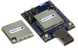
MultiTech xDot (STM32L151)
The xDot® is a low cost, low power LoRa Module.
Overview
The xDot® is a secure, CE/FCC/RCM/GITEKI certified, Arm® Mbed™ programmable, low-power RF module, that provides long-range, low bit rate M2M data connectivity to sensors, industrial equipment and remote appliances.
The xDot is LoRaWAN® 1.0.4 compliant, providing bi-directional data communication up to 10 miles/15 km line-of-sight and 1-3 miles / 2 km into buildings, using sub-GHz ISM bands in North America, Europe, Australia (AU915), Asia Pacific (AS923), India (IN865) and Korea (KR920).
xDots bring intelligence, reduced complexity and a lower overall bill of material cost to the very edge of the network while supporting a variety of electronic interfaces to connect just about any “Thing” for years on battery power.
Actual performance speeds may be affected by a variety of attributes such as distance from gateway, data loads, packet sizes, etc. Note: AS923 models are for use in many Asia Pacific countries. At this time regulatory approvals are pending. Contact your MultiTech sales representative for more information.
Key Benefits
- Excellent performance in harsh radio environments
- Range of miles
- Deep in-building penetration - 1 to 3 miles / 2 km
- Developer friendly to integrate and quickly deploy assets
- Run for years on battery power
Features
- FCC/CE/RCM/GITEKI certified for use in North America, Europe, Australia and Japan
- LoRaWAN CertifiedCM
- Unicast and Multicast message support
- Multiple I/O interfaces for connecting almost any "Thing"
- Data rates 293bps - 20Kbps + LoRa®
xDots can be purchased as standalone modules for design-in or mounted on the xDot-DK developer board.
Windows 7 Serial Driver
The mbed serial driver must be installed on windows 7 PCs before the USB debug serial port from the xDot can be used.
Offline Development Options
It is possible to develop offline for the xDot using mbed-cli and the Eclipse IDE. See our wiki page for more information.
Radio Compliance
MultiTech has certified the xDot for compliance with US and Foreign compliance bodies including FCC, R&TTE, and others. (e.g. FCC 15.247:2015 & IC RSS-210:2010)
MultiTech provides software meant to operate the LoRa radio to a level that maintains compliance with the operating modes under which these radio devices were certified. To ensure this level of compliance, the software code is provided in binary form only. Users are prohibited from making any changes that affect the operation of the radio performance. Accessing or controlling the radio through any means other than the provided binary software will require the user to obtain their own intentional radiator license from the certification body governing their locality, as all precertification provided with MTDOT-x will have been made invalid.
xDot Pinout Diagram

The pinout diagram above shows the commonly used interfaces and their locations. In addition to their stated functions, all GPIO pins (PA_*, PB_*) can also be used as DigitalIn and DigitalOut interfaces.
InterruptIn Limitations
Due to the processor's architecture, only one pin of the same number (e.g. PA_1 & PB_1) may be configured as an InterruptIn. If multiple pins of the same number are configured as InterruptIn, only the last pin configured will actually trigger an interrupt in the processor. The rest will be ignored.
Pin numbers 1, 6, 7, 8, and 13 are internally used as interrupts from the LoRa radio and may not be configured as external interrupts. Doing so will break the LoRa functionality of the xDot and cause undefined behavior.
Example: If the WAKE (PA_0) pin is configured to wake the xDot from low power modes, GPIO2 (PB_0) may not be configured as an InterruptIn. Doing so will cause the WAKE pin to not wake the xDot as desired.
PwmOut Limitations
PwmOut objects using different channels of the same timer must use the same prescaler value. Each timer has a single prescaler which applies to all channels in the timer.
For STM32L15x devices, two possible prescaler values are allowed:
- 1us which allows for a period/pulse from 1us to 65535us
- 500us which allows for a period/pulse from 500us to 32.76s
5V Tolerant IO Limitations
If the external voltage on a GPIO is greater than VDD + 0.3V, use of the internal pullup or pulldown resistors could damage the xDot. External pullup or pulldown resistors should be used instead.
For more information see the notes below section 6.3.1 of the STM32L151CC Data Sheet.
xDot Features
- STM32L151CCU6 Processor
- High performance ARM® Cortex™-M3 Core
- 32MHz, 32kB RAM, 256kB Flash
- SPI (1)
- I2C (1)
- UART (2) - 1x 4-pin TX/RX/RTS/CTS, 1x 2-pin TX/RX
- PWM (7)
- ADC (12 bit ADC with 10 channels)
- DAC (12 bit DAC with 2 channels)
- GPIO (up to 19)
- Sx1272 Radio
- Range of miles
- Deep in-building penetration - 1 to 3 miles / 2 km
- 2-way duplex communication, ideal for emergency or mission-critical applications
- LoRaWAN data rates 293bps - 20 Kbps + FSK up to 300Kbps
- Power
- 2.41V to 3.57V external power
- Current (active): < 15 mA (< 25 mA with Secure Element)
- Current (sleep): < 2 uA
- Maximum of 25 mA output current sourced by any IO pin
- Maximum of 60 mA output current sourced by sum of all IO pins
- All IO pins are 3.3v tolerant
- 15 5V tolerant IO pins (see xDot Pinout Diagram)
- Internal pullup and pulldown resistors cannot be used on 5V tolerant GPIO pins when pin voltage is greater than VDD + 0.3V. See warning box above.
xDot-DK Pinout Diagram
The table on the right maps xDot-DK pin names to xDot pin names where they differ.

| xDot-DK Pin Name | xDot Pin Name |
|---|---|
| UART1_TX | UART_TX |
| UART1_RX | UART_RX |
| UART1_CTS | UART_CTS |
| UART1_RTS | UART_RTS |
| I2C0_SDA | I2C_SDA |
| I2C0_SCL | I2C_SCL |
xDot-DK Features
- xDot-DK Onboard Sensors
- ISL29011 Ambient Light Sensor datasheet
- xDot-DK Form factor
- Approximately 2" x 1.5"
- 5V USB power or 2.41V to 3.57V external power
- Please see the xDot Developer Guide if powering DK from external power
- On-board Debug and Programming Interface Circuit
- [USB MSC] Drag-n-drop programming
- [USB CDC] USB Serial Port
- [USB HID] CMSIS-DAP
LoRa Stack (libxDot)
Version 4
Dot Library versions 4.x.x are compiled with mbed-os 6. Stable production build is hosted on mbed and GitHub for convenience.
Commit messages specify the version of mbed-os it was compiled against. We recommend building your application with the version of mbed-os specified in the commit message of the version of the Dot library you're using. This will ensure that you don't run into any runtime issues caused by differences in the mbed-os versions.
Version 3
Dot Library versions 3.x.x are compiled with mbed-os 5. Stable production build is hosted on mbed and GitHub for convenience.
Supported Toolchains and Versions
Development and production builds of the Dot Library currently only support the ARMC6 and GCC_ARM toolchains. The IAR toolchain is not supported at this time. ARMC6 is suggested for production builds, it also provides reduced firmware size and RAM usage compared with GCC_ARM builds.
Stable Production Build
This build of libxDot is stable, tested, and suitable for deployment scenarios. It is hosted on mbed and GitHub for convenience.
Bleeding Edge Development Build
This build of libxDot contains bug fixes and new feature development which may not be complete. It is not guaranteed to be stable or well-tested and is not suitable for deployment scenarios. It is hosted on mbed and GitHub for convenience.
Usage
The Dot Library requires a channel plan to be injected into the LoRa stack. Available channel plans can be found be in the Dot Library repository in the plans folder.
The following code demonstrates the basics for setting up the LoRa stack.
Setting up the mDot instance
#include "mDot.h"
#include "ChannelPlans.h"

int main() {
    // use US915 plan
    lora::ChannelPlan* plan = new lora::ChannelPlan_US915();
    // use EU868 plan
    // lora::ChannelPlan* plan = new lora::ChannelPlan_EU868();
    assert(plan);

    // inject channel plan into LoRa stack
    mDot* dot = mDot::getInstance(plan);
    assert(dot);

    // your code ...

    return 0;
}
Threads
The Dot Library starts two threads. One to manage LoRa radio, MAC, and link layers. Another to manage LoRa application layer for multicast and FOTA. Each of these threads are allocated 1280 bytes for their stacks.
Limited System Memory
Due to limited system memory, stack sizes on the xDot are smaller than mbed defaults.
- Default main thread/other threads: 4kB/2kB
- xDot main thread/other threads: 2.5kB/256B
Bootloader
A bootloader binary can be specified in the project's mbed_app.json file. See this article, our example programs, and here for details.
FOTA requires an MTS Bootloader to be included in the project.
FOTA
To enable FOTA on xDot external flash storage must be provided. See this article for flash part requirements and implementing a block device in code.
Also see BlockDevice APIs.
Example Programs
The following programs support multiple Dot devices. Before examples or the AT firmware are compiled, a Dot library must be imported. See the Dot-Examples or Dot-AT-Firmware landing pages for more details.
Import programDot-Examples
Example programs for MultiTech Dot devices demonstrating how to use the Dot devices and the Dot libraries for LoRa communication.
Last commit 25 May 2021 by ![]() MultiTech
MultiTech
For mbed-os 5 use Dot-Examples revision 41.
Import programDot-AT-Firmware
AT command firmware for MultiTech Dot devices.
Last commit 06 Dec 2023 by ![]() MultiTech
MultiTech
For mbed-os 5 use Dot-AT-Firmware revision 27.
The mbed OS API References contain example code which demonstrates how to use common peripherals like Digital IO, Analog IO, Serial, SPI, I2C, PWM, RTOS, Timers, Tickers, etc.
Factory Firmware
The xDot ships from the factory pre-loaded with our custom AT Command Firmware. This firmware provides a serial AT command interface for configuring and using the xDot. It can be used in production when using a separate host processor that controls the mDot via AT commands and during development for testing LoRa transmissions. It is available here. AT command documentation is available here.
Offline IDE
It is possible to compile for the xDot and debug them on the xDot using the Eclipse IDE. See our wiki page for more information.
MTS Bootloader
The xDot can include a bootloader to allow applications to be upgraded OTA (Over The Air) or via serial without the need for a developer board. See this article and this wiki page describing how the bootloader can be used for more information.
Bootloader binaries are available on GitHub.
Technical Reference
Documentation
- xDot Quick Start Guide
- xDot Data Sheet
- xDot Developer Guide
- Includes xDot-DK schematics and board files
- MultiTech xDot AT Command Guide
Data Sheets
- STM32L151CC Web Page
- STM32L151CC Data Sheet
- STM32L151CC Reference Manual
- STM32L151CC Errata Sheet
- SX1272 Data Sheet
- ISL29011 Data Sheet
Interface Firmware
The xDot-DK has DAPLink interface firmware. Interface firmware for the xDot-DK will be included in DAPLink releases. To update the interface firmware on your xDot-DK, follow these steps:
- Download the latest release from DAPLink releases.
- Extract the zip file.
- While holding down the reset button, plug the xDot-DK into your PC. After a drive called MAINTENANCE enumerates, the reset button can be released.
- Drag and drop the new firmware onto the MAINTENANCE drive. The firmware name should be of the form <daplink version>_k20dx_xDot_0x8000.bin.
- After the new firmware programs, the XDOT drive should appear. The DETAILS.TXT file should reflect the new DAPLink firmware version.
Warning
DAPLink v0254 fails to program xDot.
Getting Started with mbed
1. Connect your microcontroller to a PC
Use the USB lead to connect your mbed to a PC. The status light will come on, indicating it has power. After a few seconds of activity, the PC will recognise the mbed Microcontroller as a standard USB drive.
 |  |
| Windows XP example | Mac OS X example |
2. Click the MBED.HTM link to get logged in
Go to the new USB Drive, and click MBED.HTM to open it in a web browser.
If you do not have an mbed account, choose "Signup", and create your mbed Account. Otherwise, log in with your normal username and password.
This will give you access to the website, tools, libraries and documentation.
PC Configuration
Your mbed Microcontroller can appear on your computer as a serial port. On Mac and Linux, this will happen by default. For Windows 7, you need to install a driver:
Windows 7
See Windows-serial-configuration for full details about setting up Windows for serial communication with your mbed Microcontroller
From a host PC to communicate with mbed you will need a terminal application. This allows the mbed Microcontroller to print to your PC screen, and for you to send characters back to your mbed.
- Terminals - Using Terminal applications to communicate between the Host PC and the mbed Micrcontroller
Some terminal programs (e.g. TeraTerm) list the available serial ports by name. However, if you do need to know the identity of the serial port so that you can attach a terminal or an application to it:
| Windows | Mac | Linux | ||||
| Find the identity of the COM port by opening ''Device Manager''. To do this navigate ''Start -> Control Panel -> System -> Hardware -> Device Manager''. | To find the device name under Mac OS X, use the command ''ls /dev/tty.usbmodem*'' | To find the device name under Linux, use the command ''ls /dev/ttyACM*'' | ||||
 |  |  |
On both Mac and Linux PCs, the port with the higher number will be the USB serial debug port. For example, if you have Linux and get ports /dev/ttyACM0 and /dev/ttyACM1, ttyACM1 will be the debug port and ttyACM0 the AT command/secondary port.
Downloading A program
1. Save a program binary (.bin) to the Platform
Download the appropriate "Hello World!" binary:
- XDOT_L151CC: mbed-os-example-blinky_xdot_l151cc.bin
Note: the source code for this program will be seen in the next section.
Save the program binary file to your mbed Microcontroller Disk, just like you would with a normal USB disk. The Status LED will flash as the PC writes the file to the Microcontroller disk. The file is now consumed.
2. Press the Reset Button
When the Reset Button in pressed, the microcontroller will be reset and the last programmed application will begin to run.
3. Hello World!
The Microcontroller is now running the program; flashing LED1 forever! If you reset the Microcontroller, or disconnect and reconnect the power, the program will simply restart.
Hello World!
[Repository '/teams/mbed-os-examples/code/mbed-os-example-blinky/' not found]
Where Next
Follow the guide to creating your own programs using the online compiler
More information can be found here.
You need to log in to post a discussion
Discussion topics
| Topic | Replies | Last post |
|---|---|---|
| bug, glitch, Issue xDot, getNextTxMs() function, serious glitch causes module to get stuck irrecoverably | 0 |
14 Jun 2017
by
 Tuomas Manninen
|
Questions
satbeer singh 5 years, 10 months ago
Peter Klein 6 years, 3 months ago
To compile a program for this board using Mbed CLI, use xdot_l151cc as the target name.
Silicon Partner
ST
A world leader in providing the semiconductor solutions that make a positive contribution to people’s lives, both today and in the future.
 Mbed Enabled
- Baseline
Mbed OS support
- Mbed OS 5.10
- Mbed OS 5.11
- Mbed OS 5.12
- Mbed OS 5.13
- Mbed OS 5.14
- Mbed OS 5.15
- Mbed OS 5.4
- Mbed OS 5.5
- Mbed OS 5.6
- Mbed OS 5.7
- Mbed OS 5.8
- Mbed OS 5.9
- Mbed OS 6.0
- Mbed OS 6.1
- Mbed OS 6.10
- Mbed OS 6.11
- Mbed OS 6.12
- Mbed OS 6.13
- Mbed OS 6.14
- Mbed OS 6.15
- Mbed OS 6.2
- Mbed OS 6.3
- Mbed OS 6.4
- Mbed OS 6.5
- Mbed OS 6.6
- Mbed OS 6.7
- Mbed OS 6.8
- Mbed OS 6.9
Example programs