MultiTech mDot
The MultiConnect® mDot™ offers significantly longer range and improved radio performance compared to traditional wireless solutions—resulting in greater transmission range and reduced capital expense.
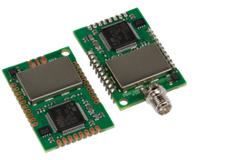
Overview
The MultiConnect® mDot™ is the first MBED integrated and deployable product. Featuring an FCC/CE certified LoRaWAN™ ready, Low-Power Wide Area Network (LPWAN) sub-GHz ISM band module. The mDot is capable of 2-way single-duplex communication over distances of up to 10 miles/16 km, line of sight, deep into buildings or within noisy environments in North America, Europe, and worldwide. An on board ARM Cortex-M4 processor, complete with developer friendly MBED libraries provide developers intelligence and decision making at the very edge of the network.
By leveraging LoRa™ technology, mDot simplifies local connectivity for Internet of Things (IoT) applications for the North American and European markets. By eliminating common deployment complexities, remote device connectivity is now simple and easy to deploy. With support for multiple interfaces, just about anything can now be connected with MultiTech’s mDot technology.
Key Benefits
- Excellent performance in harsh radio environments
- Range of miles
- Deep in-building penetration - 1 to 3 miles / 2 km
- Developer friendly to integrate and quickly deploy assets
- Run for years on battery power
Features
- XBee and module versions for development and deployment
- FCC/CE end-certified with ARM® mbed™ libraries for developers
- LoRa™ Alliance certified
- 2-way duplex communication, ideal for emergency or mission-critical applications
- Multiple I/O interfaces for most any "Thing"
- LoRaWAN data rates 293bps - 20 Kbps + FSK up to 300Kbps
Offline Development Options
It is possible to develop offline for the mDot using mbed-cli and the Eclipse IDE. See our wiki page for more information.
Developer Kit Required
To program and use the mDot, you will need a MTUDK2-ST-MDOT Developer Kit or a MTMDK-ST-MDOT.
Exporting Not Supported
When building with mbed-os 5 including a bootloader in applications built for the mDot requires a post-build process. The mbed tools (online compiler & mbed-cli) automatically run this process as part of an application compilation. The mbed tools currently don't support exporting pre-bulid or post-build processes, so exports for the mDot will be incomplete and will not function.
Exporting for the mDot platform is not recommended.
Instead of exporting, we recommend configuring your IDE or makefile to invoke mbed-cli to compile your application.
Note
MultiTech has certified the mDot for compliance with US and Foreign compliance bodies including FCC, R&TTE, and others. (e.g. FCC 15.247:2015 & IC RSS-210:2010)
MultiTech provides software meant to operate the LoRa radio to a level that maintains compliance with the operating modes under which these radio devices were certified. To ensure this level of compliance, the software code is provided in binary form only. Users are prohibited from making any changes that affect the operation of the radio performance. Accessing or controlling the radio through any means other than the provided binary software will require the user to obtain their own intentional radiator license from the certification body governing their locality, as all precertification provided with MTDOT-x will have been made invalid.
mDot Pinout Diagram

The pinout diagram above shows the commonly used interfaces and their locations. In addition to their stated functions, all GPIO pins (PA_*, PB_*, PC_*) can also be used as DigitalIn and DigitalOut interfaces.
InterruptIn Limitations
Due to the processor's architecture, only one pin of the same number (e.g. PA_1 & PB_1) may be configured as an InterruptIn. If multiple pins of the same number are configured as InterruptIn, only the last pin configured will actually trigger an interrupt in the processor. The rest will be ignored.
Pin numbers 5 - 9 are internally used as interrupts from the LoRa radio and may not be configured as external interrupts. Doing so will break the LoRa functionality of the mDot and cause undefined behavior.
Example: If the GPIO5 (PA_0) pin is configured to wake the mDot from low power modes, GPIO1 (PB_0) may not be configured as an InterruptIn. Doing so will cause the WAKE pin to not wake the mDot as desired.
PwmOut Limitations
PwmOut objects using different channels of the same timer must use the same prescaler value. Each timer has a single prescaler which applies to all channels in the timer.
For STM32F411 devices, two possible prescaler values are allowed:
- 1us which allows for a period/pulse from 1us to 65535us
- 500us which allows for a period/pulse from 500us to 32.76s
5V Tolerant IO Limitations
If the external voltage on a GPIO is greater than VDD + 0.3V, use of the internal pullup or pulldown resistors could damage the mDot. External pullup or pulldown resistors should be used instead.
For more information see the notes below section 6.3.1 of the STM32F411RE Data Sheet.
mDot Features
- STM32F411RET Processor
- High performance ARM® Cortex™-M4 Core
- 96MHz, 128kB RAM, 512kB Flash
- SPI (1)
- I2C (1)
- UART (2) - 1x 4-pin TX/RX/RTS/CTS, 1x 2-pin TX/RX
- PWM (11)
- ADC (12 bit ADC with 11 channels)
- GPIO (up to 21)
- Sx1272 Radio
- Range of miles
- Deep in-building penetration - 1 to 3 miles / 2 km
- 2-way duplex communication, ideal for emergency or mission-critical applications
- LoRaWAN data rates 293bps - 20 Kbps + FSK up to 300Kbps
- Power
- 3.3V to 5V external power
- Current (active): < 18 mA
- Current (sleep): < 50 uA
- Maximum of 25 mA output current sourced by any IO pin
- Maximum of 120 mA output current sourced by sum of all IO pins
- All IO pins are 3.3v tolerant
- 17 5V tolerant IO pins (see mDot Pinout Diagram)
- Internal pullup and pulldown resistors cannot be used on 5V tolerant GPIO pins when pin voltage is greater than VDD + 0.3V. See warning box above
LoRa Stack (libmDot)
Version 4
Dot Library versions 4.x.x are compiled with mbed-os 6. Stable production build is hosted on mbed and GitHub for convenience.
Commit messages specify the version of mbed-os it was compiled against. We recommend building your application with the version of mbed-os specified in the commit message of the version of the Dot library you're using. This will ensure that you don't run into any runtime issues caused by differences in the mbed-os versions.
Version 3
Dot Library versions 3.x.x are compiled with mbed-os 5. Stable production build is hosted on mbed and GitHub for convenience.
Supported Toolchains and Versions
Development and production builds of the Dot Library currently only support the ARMC6 and GCC_ARM toolchains. The IAR toolchain is not supported at this time. ARMC6 is suggested for production builds, it also provides reduces firmware size and RAM usage compared with GCC_ARM builds.
Stable Production Build
This build of libmDot is stable, tested, and suitable for deployment scenarios. It is hosted on mbed and GitHub for convenience.
[Repository '/teams/MultiTech/code/libmDot-stable/' not found]
Bleeding Edge Development Build
This build of libmDot contains bug fixes and new feature development which may not be complete. It is not guaranteed to be stable or well-tested and is not suitable for deployment scenarios. It is hosted on mbed and GitHub for convenience.
[Repository '/teams/MultiTech/code/libmDot-dev/' not found]
Usage
The Dot Library requires a channel plan to be injected into the LoRa stack. Available channel plans can be found be in the Dot Library repository in the plans folder.
The following code demonstrates the basics for setting up the LoRa stack and enabling FOTA support.
Setting up the mDot instance
#include "mDot.h"
#include "ChannelPlans.h"

int main() {
    // use US915 plan
    lora::ChannelPlan* plan = new lora::ChannelPlan_US915();
    // use EU868 plan
    // lora::ChannelPlan* plan = new lora::ChannelPlan_EU868();
    assert(plan);

    // inject channel plan into LoRa stack
    mDot* dot = mDot::getInstance(plan);
    assert(dot);

    // enable multicast and FOTA
    Fota::getInstance(dot);

    // your code ...

    return 0;
}
Threads
The Dot Library starts two threads. One to manage LoRa radio, MAC, and link layers. Another to manage LoRa application layer for multicast and FOTA. Each of these threads are allocated 2560 bytes for thier stacks.
Bootloader
Starting with mbed-os 6, the mDot bootloader is no longer automatically merged with the application. A bootloader binary must be specified in the project's mbed_app.json file. See this article, our example programs, and here for details.
FOTA requires an MTS Bootloader to be included in the project.
Example Programs
The following programs support multiple Dot devices. Before examples or the AT firmware are compiled, a Dot library must be imported. See the Dot-Examples or Dot-AT-Firmware landing pages for more details.
Import programDot-Examples
Example programs for MultiTech Dot devices demonstrating how to use the Dot devices and the Dot libraries for LoRa communication.
Last commit 25 May 2021 by ![]() MultiTech
MultiTech
For mbed-os 5 use Dot-Examples revision 41.
Import programDot-AT-Firmware
AT command firmware for MultiTech Dot devices.
Last commit 06 Dec 2023 by ![]() MultiTech
MultiTech
For mbed-os 5 use Dot-AT-Firmware revision 27.
The mbed OS API References contain example code which demonstrates how to use common peripherals like Digital IO, Analog IO, Serial, SPI, I2C, PWM, RTOS, Timers, Tickers, etc.
Factory Firmware
The mDot ships from the factory pre-loaded with our custom AT Command Firmware. This firmware provides a serial AT command interface for configuring and using the mDot. It can be used in production when using a separate host processor that controls the mDot via AT commands and during development for testing LoRa transmissions. It is available here. AT command documentation is available here.
Offline IDE
It is possible to compile for the mDot and debug them on the mDot using the Eclipse IDE. See our wiki page for more information.
MTS Bootloader
The mDot includes a bootloader which allows applications to be upgraded OTA (Over The Air) or via serial without the need for a developer board. See this article and this wiki page describing how the bootloader can be used for more information.
Bootloader binaries are available on GitHub.
Technical Reference
Documentation
- mDot Quick Start Guide
- mDot with Micro Developer Kit Quick Start
- mDot Datasheet
- mDot Developer Guide
- Includes UDK2 and MDK schematics and board files
- MultiTech Dot AT Command Guide
Data Sheets
- STM32F411RE Web Page
- STM32F411RE Datasheet
- STM32F411RE Reference Manual
- STM32F411RE Errata Sheet
- SX1272 Data Sheet
Interface Firmware
Both the UDK2 and MDK use the same ST-Link interface firmware as many of the ST Nucleo boards. The latest interface firmware and instructions for upgrading can be found here.
Getting Started with mbed
1. Connect your microcontroller to a PC
Use the USB lead to connect your mbed to a PC. The status light will come on, indicating it has power. After a few seconds of activity, the PC will recognise the mbed Microcontroller as a standard USB drive.
 |  |
| Windows XP example | Mac OS X example |
2. Click the MBED.HTM link to get logged in
Go to the new USB Drive, and click MBED.HTM to open it in a web browser.
If you do not have an mbed account, choose "Signup", and create your mbed Account. Otherwise, log in with your normal username and password.
This will give you access to the website, tools, libraries and documentation.
PC Configuration
Your mbed Microcontroller can appear on your computer as a serial port. On Mac and Linux, this will happen by default. For Windows, you need to install a driver:
Serial Driver for Debug Port on Windows
The DK boards for the mDot require the ST-Link driver to be installed before the debug serial port can be used on Windows PCs. This driver is different from the mbed Windows serial driver.
From a host PC to communicate with mbed you will need a terminal application. This allows the mbed Microcontroller to print to your PC screen, and for you to send characters back to your mbed.
- Terminals - Using Terminal applications to communicate between the Host PC and the mbed Micrcontroller
Some terminal programs (e.g. TeraTerm) list the available serial ports by name. However, if you do need to know the identity of the serial port so that you can attach a terminal or an application to it:
| Windows | Mac | Linux | ||||
| Find the identity of the COM port by opening ''Device Manager''. To do this navigate ''Start -> Control Panel -> System -> Hardware -> Device Manager''. | To find the device name under Mac OS X, use the command ''ls /dev/tty.usbmodem*'' | To find the device name under Linux, use the command ''ls /dev/ttyACM*'' | ||||
 |  |  |
On both Mac and Linux PCs, the port with the higher number will be the USB serial debug port. For example, if you have Linux and get ports /dev/ttyACM0 and /dev/ttyACM1, ttyACM1 will be the debug port and ttyACM0 the AT command/secondary port.
Downloading A program
1. Save a program binary (.bin) to the Platform
Download the appropriate "Hello World!" binary. Because the UDK2 and MDK have the LED connected to different pins on the mDot, we've provided a binary for each option:
- Blink the D3 LED on a UDK2: mbed-os-example-blinky_MTS_MDOT_F411RE-udk2.bin
- Blink the RSSI LED on a MDK: mbed-os-example-blinky_MTS_MDOT_F411RE-mdk.bin
Note: the source code for this program will be seen in the next section.
Save the program binary file to your mbed Microcontroller Disk, just like you would with a normal USB disk. The Status LED will flash as the PC writes the file to the Microcontroller disk. The file is now consumed.
2. Press the Reset Button
When the Reset Button in pressed, the microcontroller will be reset and the last programmed application will begin to run.
3. Hello World!
The Microcontroller is now running the program; flashing LED1 forever! If you reset the Microcontroller, or disconnect and reconnect the power, the program will simply restart.
Hello World!
[Repository '/teams/mbed-os-examples/code/mbed-os-example-blinky/' not found]
In its current state, the program will blink the D3 LED on a UDK2 board. To blink the RSSI LED on a MDK board, change the DigitalOut pin from LED1 to XBEE_RSSI.
Where Next
Follow the guide to creating your own programs using the online compiler
More information can be found here.
FAQ
- What is Spreading Factor? Bandwidth?
- Spreading Factor: Basically the amount of redundant data that is transmitted. Higher spreading factor, less data rate and longer range (e.g. more redundant data).
- Bandwidth: The frequency range (in hertz) of the transmitted signal.
- How many mDots can attach to a MultiConnect Conduit with LoRa support (e.g. MTAC-LORA)?
- Approximately 3500 mDots per MTAC-LORA card. A Conduit can support 1 MTAC-LORA card.
- Will the MultiConnect Conduit with LoRa support (e.g. MTAC-LORA) work with Microchip LoRa?
- The MTAC-LORA card is compatible with any device that is LoRaWAN 1.0 compliant.
- Can I configure the mDots and mCards for LoRa spread spectrum mode or FSK mode?
- Yes, either mode is possible. The mDot can be configured for either FSK or LoRa mode, but not both at the same time. The MTAC-LORA card has eight LoRa receive channels, one LoRa Beacon channel, and one FSK channel.
- What is the LoRa transport packet size?
- The maximum transport packet size is 255 bytes plus preamble. But, due to on-air transmission restrictions, the maximum packet size may be smaller. Higher spreading factors, lower data rates, and longer preamble lengths will reduce the maximum allowed transport packet size.
- How much payload in each LoRa packet?
- The maximum payload is 242 bytes.
- Is there a way to increase the limit/size of the payload?
- The major limit to packet size is due to on-air time or duty cycle restrictions. It is not possible to increase the packet size and maintain FCC or ETSI certification.
- Is there a minimum waiting between transmission from the client radio?
- The radio waits for incoming packets for 2 seconds after a transmission. You can disable the receive timeout using the AT+TXW command. This parameter can be changed based on the LoRaWAN 1.0 specification.
- What kind of security does LoRa provide? Is the data encrypted?
- Transmitted data is not encrypted. Most applications handle encryption so it's not needed at the transport layer. However, AES128 bit encryption is supported if needed in LoRaWAN 1.0.
- Do all LoRa gateways in range see all mDots in the field? How would I isolate my mDots so other gateways don't receive my data?
- Since this is RF, all gateways in range of an mDot would see the mDot. Packet encryption, network keys, and channel selection can be used to force an mDot to only communicate with one gateway. Encryption keys are generated when an mDot joins a specific network using nonce values and a pre-shared network key. If each gateway in range of an mDot uses a different encryption key, they will only be able to process packets from mDots with matching keys.
- Does mDot/MTAC-LORA send bidirectional data? Is it half-duplex or full-duplex communication?
- Since this is single-channel RF on the mDot side, all communication is half-duplex.
- Can the LoRa gateway interrogate mDots in the field or are only the mDots able to initiate communication to the Gateway?
- Yes, the gateway can transmit data to the mDots. The MTAC-LORA card has a single beacon transmit channel that can transmit to 1 or more mDots.
- How long does the mDot wait for a response to the packet I sent? Is there anything I can do if I want to send packets faster than that?
- The mDot waits for a response until both receive windows have expired. This is approximately 2 seconds. If you aren't expecting responses to your packets, you can disable the receive timeout using the AT+TXW command.
- For Serial mode, is this like setting up a stream that will transmit when the SDxx values are met? Serial mode still has a packet and payload?
- LoRa transmits only in packets. There are limits on the size of a packet based on on-air time restrictions. In serial mode the mDot will wakeup at the expiration of the +WI value. It will set the XBEE_ON_SLEEP pin, and wait the +WD value in ms. Then it will read the serial data until the +WTO time elaspses without a byte on the serial port. It will place the recv'd data into a packet and send it out the radio.
- What is the working limits and differences between AT mode and Serial mode?
- Serial mode will automatically packetize data from the serial port and send based on the settings for:
- AT+WI - how often to expect data
- AT+WTO - timeout between characters to know end of data
- AT+WD - time to wait at beginning of interval for data to arrive on serial
- Serial mode will only send one packet per time period set by the AT+WI command.
- AT mode will send packets as fast as the controlling system can send them within the confines of physical limitations and FCC regulations.
- Serial mode will automatically packetize data from the serial port and send based on the settings for:
You need to log in to post a discussion
Discussion topics
| Topic | Replies | Last post |
|---|---|---|
| Errors, link, mbed-cli, MBED-OS, mdot, multitech Multiple definition Link error with mbed-cli | 1 |
19 Nov 2018
by
 Jason Reiss
|
| InterruptIn, mdot how to wakeup a mDot through multiple InterruptIn pins? | 0 |
21 Oct 2018
by
 Lo Che
|
Questions
xudong song 5 years, 2 months ago
Ajay Kashyap 5 years, 8 months ago
To compile a program for this board using Mbed CLI, use mts_mdot_f411re as the target name.
Silicon Partner
ST
A world leader in providing the semiconductor solutions that make a positive contribution to people’s lives, both today and in the future.
 Mbed Enabled
- Baseline
Mbed OS support
- Mbed OS 5.10
- Mbed OS 5.11
- Mbed OS 5.12
- Mbed OS 5.13
- Mbed OS 5.14
- Mbed OS 5.15
- Mbed OS 5.4
- Mbed OS 5.5
- Mbed OS 5.6
- Mbed OS 5.7
- Mbed OS 5.8
- Mbed OS 5.9
- Mbed OS 6.0
- Mbed OS 6.1
- Mbed OS 6.2
- Mbed OS 6.3
- Mbed OS 6.4
- Mbed OS 6.5
- Mbed OS 6.6
- Mbed OS 6.7
- Mbed OS 6.8
Example programs