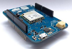
L-Tek FF1705
The L-Tek FF1705 platform is based on the low cost, low power MultiConnect® xDot™ Module from MultiTech, complete with an integrated DAPLink interface, all in an Arduino form factor.

Overview
The L-Tek FF1705 is a development platform for the MultiConnect® xDot™, an ARM® mbed™ programmable, low-power RF module, that provides long-range, low bit rate M2M data connectivity to sensors, industrial equipment and remote appliances.
Conveniently integrated with a DAPLink programming and debug interface, and complete with Arduino compatible headers, this platform can be used to prototype applications using a wide range of IO boards and peripherals supported by mbed in the mbed Component library.
Additionally, this platform can be used as a shield when fitted to an Arduino form-factor MCU development platform by running the MultiTech AT Command Firmware.
See the Factory Firmware section below for more details.
Windows Serial Driver
The mbed serial driver must be installed on windows PCs before the USB debug serial port from the xDot can be used.
Offline Development Options
It is possible to develop offline for the xDot using mbed-cli and the Eclipse IDE. See wiki page for more information.

The pinout diagram above shows the commonly used interfaces and their locations. In addition to their stated functions, all GPIO pins (PA_*, PB_*) can also be used as DigitalIn and DigitalOut interfaces.
InterruptIn Limitations
Due to the processor's architecture, only one pin of the same number (e.g. PA_1 & PB_1) may be configured as an InterruptIn. If multiple pins of the same number are configured as InterruptIn, only the last pin configured will actually trigger an interrupt in the processor. The rest will be ignored.
Pin numbers 1, 6, 7, 8, and 13 are internally used as interrupts from the LoRa radio and may not be configured as external interrupts. Doing so will break the LoRa functionality of the xDot and cause undefined behavior.
Example: If the WAKE (PA_0) pin is configured to wake the xDot from low power modes, GPIO2 (PB_0) may not be configured as an InterruptIn. Doing so will cause the WAKE pin to not wake the xDot as desired.
PwmOut Limitations
PwmOut objects using different channels of the same timer must use the same prescaler value. Each timer has a single prescaler which applies to all channels in the timer.
For STM32L15x devices, two possible prescaler values are allowed:
- 1us which allows for a period/pulse from 1us to 65535us
- 500us which allows for a period/pulse from 500us to 32.76s
5V Tolerant IO Limitations
If the external voltage on a GPIO is greater than VDD + 0.3V, use of the internal pullup or pulldown resistors could damage the xDot. External pullup or pulldown resistors should be used instead.
For more information see the notes below section 6.3.1 of the STM32L151CC Data Sheet.
mbed Library Limitations
This platform exclusively supports mbed OS version 5. It is compatible with the mbed-os library available to import from https://github.com/armmbed/mbed-os. The use of the mbed 2 SDK "classic" library will result in an error. Most of the APIs are compatible between mbed versions, but please remember to use the right mbed library (mbed-os).
xDot Features
- STM32L151CCU6 Processor
- High performance ARM® Cortex™-M3 Core
- 32MHz, 32kB RAM, 256kB Flash
- SPI (1)
- I2C (1)
- UART (2) - 1x 4-pin TX/RX/RTS/CTS, 1x 2-pin TX/RX
- PWM (7)
- ADC (12 bit ADC with 10 channels)
- DAC (12 bit DAC with 2 channels)
- GPIO (up to 19)
- Sx1272 Radio
- Range of miles
- Deep in-building penetration - 1 to 3 miles / 2 km
- 2-way duplex communication, ideal for emergency or mission-critical applications
- LoRaWAN data rates 293bps - 20 Kbps + FSK up to 300Kbps
- Power
- 2.41V to 3.57V external power
- Current (active): < 15 mA (< 25 mA with Secure Element)
- Maximum of 25 mA output current sourced by any IO pin
- Maximum of 60 mA output current sourced by sum of all IO pins
- All IO pins are 3.3v tolerant
- 15 5V tolerant IO pins (see xDot Pinout Diagram)
- Internal pullup and pulldown resistors cannot be used on 5V tolerant GPIO pins when pin voltage is greater than VDD + 0.3V. See warning box above.
FIRMWARE UPGRADE - DAPLink Interface
The FF1705 includes the DAPLink interface. Firmware for the FF1705 will be included in DAPLink releases. To update the interface firmware on your FF1705, follow these steps:
- Hold 'RESET' button down on FF1705
- Plug the FF705 into PC via micro USB
- Observe drive "CRP 'DISABLD'
- Open the drive, and delete the file called "firmware.bin"
- Download the required firmware
- Copy the .bin file onto the "CRP DISABLD" drive.
- On Windows, replace firmware.bin with the above firmware
- On Linux/Mac, use command: dd if={new_firmware.bin} of={firmware.bin} conv=notrunc
- Unplug your FF1705, and plug it back in
- It should now appear as a disk drive called FF1705 (DAPLink)
You can re-program your FF1705 at any time by plugging it in with the button held down. This will cause it to appear as the "CRP DISABLD" drive, at which point you can follow the steps above.
Example Programs
The following programs support multiple Dot devices. Before examples or the AT firmware are compiled, a Dot library must be imported.
[Repository '/teams/MultiTech/code/libxDot-dev-mbed5/' not found]
See the Dot-Examples or Dot-AT-Firmware landing pages for more details. Dot-Examples rev. 31:7ec180e84cb6 have been tested with xdot-library 3.0.0-19-gb6c0ba2 and mbed-os-5.6.2
Import programDot-AT-Firmware
AT command firmware for MultiTech Dot devices.
Last commit 06 Dec 2023 by ![]() MultiTech
MultiTech
Download compiled Dot-AT-Firmware here. AT documentation is available here
For sending AT commands use the serial interface on arduino headers: uart_tx, uart_rx
The mbed OS API References contain example code which demonstrates how to use common peripherals like Digital IO, Analog IO, Serial, SPI, I2C, PWM, RTOS, Timers, Tickers, etc.
LoRaWan
Build Applications:
- Efficient and environment friendly cities
- smart parking meters, tollbooths, traffic signals
- Safety Applications:
- forest fire, floods, avalancehs and other natural disasters can be detected before they happen or get out of control
- Monitoring:
- tracking people and pets, cattle tracking, locating items
- gas, water flow monitoring

Build Your Own Private LoRa Network
https://docs.mbed.com/docs/lora-with-mbed/en/latest/intro-to-lora/

AT Command Firmware
This firmware provides a serial AT command interface for configuring and using the xDot. This firmware is great during development for testing LoRa transmissions and in production when using a separate host processor that controls the xDot via AT commands. It is available here. AT command documentation is available here. The AT commands must be sent to uart_tx, uart_rx over usb-to-uart adapter.
Technical Reference
Documentation
- xDot Quick Start Guide
- xDot Data Sheet
- xDot User's Manual
- Includes xDot-DK schematics and board files
- MultiTech Dot AT Command Guide
Data Sheets
- STM32L151CC Web Page
- STM32L151CC Data Sheet
- STM32L151CC Reference Manual
- STM32L151CC Errata Sheet
- SX1272 Data Sheet
- ISL29011 Data Sheet
Getting Started with mbed
1. Connect your microcontroller to a PC
Use the USB lead to connect your mbed to a PC. The status light will come on, indicating it has power. After a few seconds of activity, the PC will recognise the mbed Microcontroller as a standard USB drive.
 |  |
| Windows XP example | Mac OS X example |
2. Click the MBED.HTM link to get logged in
Go to the new USB Drive, and click MBED.HTM to open it in a web browser.
If you do not have an mbed account, choose "Signup", and create your mbed Account. Otherwise, log in with your normal username and password.
This will give you access to the website, tools, libraries and documentation.
PC Configuration
Your mbed Microcontroller can appear on your computer as a serial port. On Mac and Linux, this will happen by default. For Windows, you need to install a driver:
Windows
See Windows-serial-configuration for full details about setting up Windows for serial communication with your mbed Microcontroller
From a host PC to communicate with mbed you will need a terminal application. This allows the mbed Microcontroller to print to your PC screen, and for you to send characters back to your mbed.
- Terminals - Using Terminal applications to communicate between the Host PC and the mbed Micrcontroller
Some terminal programs (e.g. TeraTerm) list the available serial ports by name. However, if you do need to know the identity of the serial port so that you can attach a terminal or an application to it:
| Windows | Mac | Linux | ||||
| Find the identity of the COM port by opening ''Device Manager''. To do this navigate ''Start -> Control Panel -> System -> Hardware -> Device Manager''. | To find the device name under Mac OS X, use the command ''ls /dev/tty.usbmodem*'' | To find the device name under Linux, use the command ''ls /dev/ttyACM*'' | ||||
 |  |  |
On both Mac and Linux PCs, the port with the higher number will be the USB serial debug port. For example, if you have Linux and get ports /dev/ttyACM0 and /dev/ttyACM1, ttyACM1 will be the debug port and ttyACM0 the AT command/secondary port.
Downloading A program
1. Save a program binary (.bin) to the Platform
Download the appropriate "Hello World!" binary:
- XDOT_L151CC: mbed-os-example-blinky_xdot_l151cc.bin
Note: the source code for this program will be seen in the next section.
Save the program binary file to your mbed Microcontroller Disk, just like you would with a normal USB disk. The Status LED will flash as the PC writes the file to the Microcontroller disk. The file is now consumed.

2. Press the Reset Button
When the Reset Button in pressed, the microcontroller will be reset and the last programmed application will begin to run.
3. Hello World!
The Microcontroller is now running the program; flashing LED1 forever! If you reset the Microcontroller, or disconnect and reconnect the power, the program will simply restart.
Hello World!
[Repository '/teams/mbed-os-examples/code/mbed-os-example-blinky/' not found]
Where Next
Follow the guide to creating your own programs using the online compiler
Schematics
The FF1705 is an open hardware design delivered as part of the mbed-HDK
You need to log in to post a discussion
Discussion topics
| Topic | Replies | Last post |
|---|---|---|
| deep sleep, DeepSleep, FF1705, low power, low power operation, Sleep FF1705 Low Power Mode | 2 |
06 Apr 2018
by
 Gorazd Kovacic
|
Questions
To compile a program for this board using Mbed CLI, use FF1705_L151CC as the target name.
Board Partner
L-Tek
L-Tek is engaged in the development and production of electronic modules and electromechanical components for the electronics industry.
Silicon Partner
ST
A world leader in providing the semiconductor solutions that make a positive contribution to people’s lives, both today and in the future.
Mbed OS support
- Mbed OS 5.10
- Mbed OS 5.11
- Mbed OS 5.12
- Mbed OS 5.13
- Mbed OS 5.14
- Mbed OS 5.15
- Mbed OS 5.5
- Mbed OS 5.6
- Mbed OS 5.7
- Mbed OS 5.8
- Mbed OS 5.9