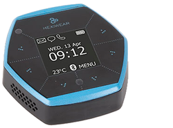
Hexiwear
Next generation wearable IoT development platform designed to reduce time to market. Comes in compact form factor with on-board MCUs, BLE connectivity, sensors, OLED display, and battery. Open source software package includes embedded software, cellphone apps and cloud connectivity. Expandable with 200 additional click boards™.
Quote:
Looking for mbed examples or applications to start programming your Hexiwear platform, jump directly to the HEXIWEAR CODE REPOSITORY
Overview
Hexiwear has been designed by MikroElektronika in collaboration with NXP to better support developer projects by accelerating their time to market, reducing their development and manufacturing costs and securing their migration from prototype to production. For just $49, this open-source reference-design for IoT/connected applications brings together everything developers need to design their next IoT application in a very compact form factor (2" x 2").
Featuring more than traditional MCU development platforms, the Hexiwear platform is ideal for connected applications, thanks to its power-efficient Kinetis K64F MCU featuring:
- ARM® Cortex®-M4 core;
- max frequency up to 120MHz;
- 1024KB Flash, 256KB RAM;
- many peripherals (16-bit ADCs, DAC, Timers);
- interfaces (USB Device Crystal-less, UART, SPI, I2C, I2S, SD-card).
Integration is also a key feature of Hexiwear, with a Bluetooth Low Energy (BLE) SoC (Kinetis KW40z) and 8 Sensors onboard:
- 6-axis Accelerometer and Magnetometer combo (FXOS8700CQ);
- 3-axis Gyroscope (FXAS21002CQ);
- Pressure sensor accurate up to Altitude sensing (MPL3115A2);
- Temperature and humidity combo (HTU21D);
- Ambient light sensor (TSL2561);
- Optical Heart rate sensor (Maxim MAX30101).
It also includes a 1.1” OLED color display and a 190mAh 2C Li-Po battery with a charger (MC34671) (see block diagram below).
The Kinetis K64 MCU family remains fully software, hardware and development tool compatible with Kinetis MCUs, and existing NXP Freedom projects (using the FRDM-K64F Freedom platform) can be easily migrated to Hexiwear.
The docking station for Hexiwear allows developers to easily program and debug their code (built-in USB Debug and Flash Programmer) and expand the board features with up to three click boards™ among a portfolio of more than 200 references.
MCU Features
- Kinetis MK64FN1M0VDC12 in 121BGA
- Performance
- ARM® Cortex®-M4 32-bit core with DSP instructions and Floating Point Unit (FPU)
- 120 MHz max CPU frequency
- Memories and memory interfaces
- 1024 KB program flash memory
- 256 KB RAM
- FlexBus external bus interface
- System peripherals
- Multiple low-power modes, low-leakage wake-up unit
- 16-channel DMA controller
- Clocks
- 3x Internal Reference Clocks: 32KHz, 4MHz and 48MHz
- 2x Crystal inputs: 3-32MHz (XTAL0) and 32kHz (XTAL32/RTC)
- PLL and FL
- Analog modules
- 2x 16-bit SAR ADCs up 800ksps (12-bit mode)
- 2x 12-bit DACs
- 3x Analog comparators
- Voltage reference 1.13V
- Communication interfaces
- 1x 10/100 Mbit/s Ethernet MAC controller with MII/RMII interface IEEE1588 capable
- 1x USB 2.0 Full-/Low-Speed Device/Host/OTG controller with embedded 3.3V/120mA Vreg, and USB device Crystal-less operation
- 1x Controller Area Network (CAN) module
- 3x SPI modules
- 3x I2C modules. Support for up to 1 Mbit/s
- 6x UART modules
- 1x Secure Digital Host Controller (SDHC)
- 1x I2S module
- Timers
- 2x 8-channel Flex-Timers (PWM/Motor control)
- 2x 2-channel FlexTimers (PWM/Quad decoder)
- 32-bit PITs and 16-bit low-power timers
- Real-Time Clock (RTC)
- Programmable delay block
- Security and integrity modules
- Hardware CRC and random-number generator modules
- Hardware encryption supporting DES, 3DES, AES, MD5, SHA-1 and SHA-256 algorithms
- Operating Characteristics
- Voltage range: 1.71 to 3.6 V
- Flash write voltage range: 1.71 to 3.6 V
Board Features
- Hexiwear Components
- Kinetis MK64FN1M0VDC12 - ARM® Cortex®-M4 @120MHz 32-bit main MCU with 1024KB Flash and 256KB RAM memory
- FXOS8700CQ - 6-axis combo Sensor Accelerometer and Magnetometer
- FXAS21002CQ - 3-axis Gyroscope
- FXAS21002CQ - pressure sensor accurate up to Altitude sensing
- HTU21D - combo temperature and Humidity
- TSL2561 - ambient light sensor and
- MAX30101 - optical Heart rate sensor
- W25Q64FVSSIG - 8MB/64Mbit Serial Flash memory
- 6 user capacitive/touch electrodes (controlled by KW40z Wireless SoC)
- RGB LED
- Vibration motor for haptic feedback
- Hexiwear Connectivity
- Kinetis MKW40Z160VHT4 - 2,4GHz Wireless SoC Bluetooth Low-Energy (BLE) v4.1 (default) and 802.15.4 capable
- Up to 5x UARTs, 1x SPI, 2x I2Cs and 1x CAN connected to Headers (multiplexed peripherals)
- I2S interface (pinout on Docking station)
- Extensions
- Micro SD-Card (Socket on Docking station)
- 3x mikro-bus sockets to combine click boards™ among a portfolio of 200 references (Headers on Docking station)
- Analog and Digital I/O (multiplexed peripherals)
- Up to two ADC 16-bit resolution with 8 Analog Pins connected to Headers
- Up to four timers with 10 PWM signals accessible from Headers
- Up to three Comparators with 6 Inputs
- Up to 31 MCU I/O Pins connected to Headers (3.3v, 25mA each, 100mA max total)
- Board power supply options (onboard 5 to 3.3V regulator)
- Embedded 190 mAh 2C Li-Po battery
- Docking USB Debug port (charge enabled)
- Hexiwear USB port (charge enabled)
- OpenSDA USB Debug and Programming adapter (available via the Docking Station)
- Several industry standard Debug interfaces (PEmicro, CMSIS-DAP, JLink)
- Drag-n-drop MSD Flash-programming
- Virtual USB to Serial Port
- Form factor: 2in x 2in / 5.08cm x 5.08cm
- Software Development Tools
- mbed-Enabled(TM) (HDK, SDK, online development tools, community)
- Easy to use C/C++ SDK
- Many published libraries and projects
- Alternate offline options using NXP Kinetis Design Studio IDE (free compiler toolchain) and Kinetis SDK library/examples
- Supplier website: http://www.hexiwear.com
- Status
- Available Now
Board Block Diagram
The graphic below gives an overview of the board features and the connection between the target MCU and the on-board components and connectors

Board Pinout
Component Pinout
Following figure indicates the Kinetis K64F signal connections with the board components (RGB LED, Sensors, Display, Memory...)

Docking Header Pinout
Docking headers enable up to 58-pins and give access to most of the Kinetis K64F signals via
- three Click module sockets
- one I2S header (not populated)

Important Notes
Please note that on this MCU in SPI Slave mode pins labeled MOSI behave as Slave Output and pins labeled MISO behave as Slave Input. The terms MOSI (Master Out Slave In) and MISO (Master In Slave Out) only apply to Master mode.
Docking switches authorize user to select the microcontroller (K64F or KW40Z) to be programmed/debugged, the onboard OpenSDA or external debugger and enable the I2S or the Push buttons.

Hexiwear Docking Station is fully supported in the mbed Developer Platform with full access to the free tools and mbed SDK, providing experienced embedded developers with powerful and productive tools for building "proof-of-concepts". The pinout above shows the commonly used interfaces and their locations. Note that all the numbered pins (PT_XX) can also be used as DigitalIn and DigitalOut interfaces.
Pin names
PC Configuration
The Docking station embeds (on the back) a controller, which emulates the latest ARM DAP-LINK debug interface, featuring MSD Flash programming, Debug and virtual Serial Serial port. You must connect your computer via the USB cable to the micro-USB port of the Docking station. Make sure that the PWR switch of the Docking station is set ON and the green PWR status light will come on, indicating it has power. The MSD drive and the Debugger are automatically detected however the Virtual Serial port must be properly setup for your computer. On Mac and Linux, this will happen by default. For Windows, you need to install a driver:
Windows
See Windows-serial-configuration for full details about setting up Windows for serial communication with your mbed Microcontroller
From a host PC to communicate with mbed you will need a terminal application. This allows Hexiwear via the micro-USB port of the Docking station to print to your PC screen, and for you to send characters back to your mbed.
- Terminals - Using Terminal applications to communicate between the Host PC and the Hexiwear via the micro-USB port of the Docking station.
Some terminal programs (e.g. TeraTerm) list the available serial ports by name. However, if you do need to know the identity of the serial port so that you can attach a terminal or an application to it:
| Windows | Mac | Linux | ||||
| Find the identity of the COM port by opening ''Device Manager''. To do this navigate ''Start -> Control Panel -> System -> Hardware -> Device Manager''. | To find the device name under Mac OS X, use the command ''ls /dev/tty.usbmodem*'' | To find the device name under Linux, use the command ''ls /dev/ttyACM*'' | ||||
 |  |  |
Get Started with mbed
1. First board connection
Plug Hexiwear on the Docking station and connect the one end of the USB cable to your computer and the other end to the micro-USB port of the Docking station. Make sure that the PWR switch of the Docking station is set ON and the green PWR status light will come on, indicating it has power. After a few seconds of activity, the PC will recognize the mbed Microcontroller as a standard USB drive called "DAP-LINK".
 |  |
| Windows XP example | Mac OS X example |
2. Connect to mbed
Go to the new USB Drive, and click MBED.HTM to open it in a web browser.
If you do not have an mbed account, choose "Signup", and create your mbed Account. Otherwise, log in with your established mbed username and password.
This will give you access to the website, tools, libraries and documentation.
Flash a project binary
1. Download a (.bin) to Hexiwear
Download the appropriate "Hello World!" binary:
- MikroElektronika HEXIWEAR: HelloWorld_Hexi_K64F.bin
Note: the source code for this program will be seen in the next section.
Save the program binary file to the DAP-LINK disc from your file explorer, just like you would with a normal USB disk.

2. Press the Reset Button
When the Reset_K64F Button located on the Docking station is pressed, the newest program on the DAP-LINK drive will be loaded in to the K64F microcontroller FLASH memory.
When the program is has been loaded onto the K64F microcontroller, it will then start it running.
3. Run Hello World!
The K64F microcontroller is now running the program; Blink LED Red forever! If you reset the K64F microcontroller, or disconnect and reconnect the power, the program will simply restart.
4. Flash a new precompiled program
It is the newest program on the K64F microcontroller that is run after reset. We can therefore download a new program or overwrite an existing one to update the program that will run.
Hexiwear factory demo
The binary for the default project programmed in factory in Hexiwear memory is available for download at the end of this page.
Open existing Project
1. Import the Program to your mbed compiler
Select Import As Program
Choose Import Name of your preference
Click on Import
Import programHexi_Blinky_Example
Blinky program example for Hexiwear
Last commit 12 Aug 2016 by ![]() Hexiwear
Hexiwear
2. Compile the Program
In the right panel Program Workspace Select the program you want to compile
Click on Compile in toolbar
If compilation ends successfully, you should see the comment Success! displayed in the Compile Output window available in the bottom and your web browser should download automatically the precompiled binary for the program.
3. Download a (.bin) to Hexiwear
Save the program binary file to the DAP-LINK drive from your file explorer, just like you would with a normal USB disk. The Status LED will flash as the PC writes the file to the Microcontroller disk.
4. Press the Reset Button
When the Reset_K64F Button located on the Docking station is pressed, the newest program on the DAP-LINK drive will be loaded in to the K64F microcontroller FLASH memory. The Status LED will flash as this happens. When the program has been loaded onto the K64F microcontroller, it will then start it running.
5. Run the Program
The K64F microcontroller is now running the program; flashing LED1/Red located on Hexiwear front panel forever! If you reset the K64F microcontroller, or disconnect and reconnect the power, the program will simply restart.
Program Examples
Congratulations, you have successfully compiled your first project example, you will find more program examples for the Hexiwear board available on the right panel of this page or at the Hexiwear code repository
Create new Project
Follow the guide to creating your own programs using the online compiler
Technical Doc
Hexiwear Board
Kinetis K64F MCU
- Data Sheet
- Reference Manual
- Errata
- AN4470 - Using Low-Power Modes with Kinetis MCUs
- AN5083 - Using DMA for pulse counting
- AN4373 - Cookbook for SAR ADC
- AN4381 - FlexTimer configuration
FXOS8700CQ 6-axis combo Accelero and Magnetometer
FXAS21002CQ 3-axis Gyroscope
MPL3115A2 Pressure sensor with Altimeter capabilities
HTU21D Temperature and Humidity sensor
TSL2561 Ambient light Sensor
MAX30101 Optical Heart rate Sensor
KW40Z BLE v4.1 and 802.15.4 Wireless 2.4GHz SoC
PSP27801 OLED color display
W25Q64FVSSIG 8MB/64Mbit Serial Flash memory
Software Materials
Hexiwear Factory Program
Hexiwear Interface Firmware / OpenSDA Application
- DAP-LINK Interface Firmware for the docking (updated version 24 April 2018)
Combining DAP-LINK debug, MSD flash programming and Serial features for both K64F and KW40Z MCUs
K64F Freedom Sensor Libraries and Examples
- FXOS8700Q - 6 Axis combination Accelerometer / Magnetometer for eCompass
FXOS8700Q Driver Library and Example program
- eCompass - A basic eCompass using the on board FXOS8700Q
eCompass Library for Cortex-M4F and eCompass Example program
- Differential A2D - Library and example to use the 16 Bit Differential A2D on the K64
Differential A2D Library for K64F and Differential A2D Example program
Hexiwear basic program examples
Import programHexi_Timer_Example
Timer program example for Hexiwear
Last commit 15 Aug 2016 by ![]() Hexiwear
Hexiwear
Import programHexi_Serial_Example
Serial program example for Hexiwear
Last commit 15 Aug 2016 by ![]() Hexiwear
Hexiwear
Import programHexi_Serial_Rgb_Example
Serial and RGB LED program example for Hexiwear
Last commit 15 Aug 2016 by ![]() Hexiwear
Hexiwear
Import programHexi_Accelero_Magneto_Example
Simple accelerometer and magnetometer program example for Hexiwear featuring UART
Last commit 15 Aug 2016 by ![]() Hexiwear
Hexiwear
Import programHexi_Gyro_Example
Simple gyroscope program example for Hexiwear featuring UART
Last commit 15 Aug 2016 by ![]() Hexiwear
Hexiwear
Import programHexi_Pressure_Baro_Temp_Example
Barometric pressure and temperature sensing program example for Hexiwear
Last commit 15 Aug 2016 by ![]() Hexiwear
Hexiwear
Hexiwear application examples
Import programHexi_Accelero_Magneto_Example
Simple accelerometer and magnetometer program example for Hexiwear featuring UART
Last commit 15 Aug 2016 by ![]() Hexiwear
Hexiwear
Import programHexi_Gyro-v2_Example
Advanced gyroscope program example for Hexiwear featuring OLED Display
Last commit 19 Oct 2016 by ![]() Hexiwear
Hexiwear
Import programHexi_Pressure_Baro_Temp_Example
Barometric pressure and temperature sensing program example for Hexiwear
Last commit 15 Aug 2016 by ![]() Hexiwear
Hexiwear
Import programHexi_Humid_Temp-v2_Example
Advanced temperature and humidity program example for Hexiwear featuring OLED Display
Last commit 17 Oct 2016 by ![]() Hexiwear
Hexiwear
Import programHexi_BLE_Example
Hexiwear Bluetooth Low Energy Example. The device is configured to behave as a sensor tag. This example is to be used with the Hexiwear mobile app on iOS and Android.
Last commit 26 Sep 2016 by ![]() Hexiwear
Hexiwear
Import programHexi_OLED_Text_Example
Example shows how to display static and dynamic text on the Hexiwear OLED Display.
Last commit 28 Aug 2016 by ![]() Hexiwear
Hexiwear
Import programHexi_OLED_Image_Example
Displays a full size image (96px by 96px) on the Hexiwear OLED display then displays a smaller image (96px by 32px) on the bottom portion of the display.
Last commit 28 Aug 2016 by ![]() Hexiwear
Hexiwear
Import programHexi_OLED_TextImage_Example
Example showing usage of text and image. Builds on the text example with a banner image at the bottom of the screen.
Last commit 28 Aug 2016 by ![]() Hexiwear
Hexiwear
Import programHexi_Buttons_Example
Basic touch buttons example for Hexiwear
Last commit 19 Sep 2016 by ![]() Hexiwear
Hexiwear
Import programHexi_Vibration_Example
Haptic feedback example for Hexiwear
Last commit 19 Aug 2016 by ![]() Hexiwear
Hexiwear
Supported Mikroe Click modules
MIKROELEKTRONIKA introduced few years ago a new family called CLICK of compact Connectivity and Sensor modules, much cheaper (starting $5) and smaller than Arduino shields. Up to now the Mikroe Click portfolio includes more than 200 extension solutions!!
Please find below the list of the Program Examples tested with Hexiwear
User Interfaces
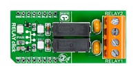
![]() Hexi Click Relay Example
Hexi Click Relay Example
Control two Relays using Touch electrodes and Display Relays status (instructions available).
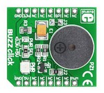
![]() Hexi Click Buzzer Example
Hexi Click Buzzer Example
Play some tones with Buzzer using Touch electrode to start it and Display Buzzer status (instructions available).
Assistance
Hexiwear factory demo
Restore Hexiwear in default state downloading/programming Hexiwear default/original demo
You need to log in to post a discussion
Discussion topics
| Topic | Replies | Last post |
|---|---|---|
| Screen Blank Problem | 0 |
11 Jan 2018
by
 D J
D J
|
| Programming and Serial Port via uUSB connector | 0 |
16 Dec 2016
by
Hans Oppermann
|
Questions
German Rivera 6 years, 4 months ago
vasanth kumar 7 years, 2 months ago
To compile a program for this board using Mbed CLI, use hexiwear as the target name.
 Mbed Enabled
- Baseline
Mbed OS support
- Mbed OS 5.10
- Mbed OS 5.11
- Mbed OS 5.12
- Mbed OS 5.13
- Mbed OS 5.14
- Mbed OS 5.15
- Mbed OS 5.4
- Mbed OS 5.5
- Mbed OS 5.6
- Mbed OS 5.7
- Mbed OS 5.8
- Mbed OS 5.9
- Mbed OS 6.0
- Mbed OS 6.1
- Mbed OS 6.10
- Mbed OS 6.11
- Mbed OS 6.12
- Mbed OS 6.13
- Mbed OS 6.14
- Mbed OS 6.15
- Mbed OS 6.2
- Mbed OS 6.3
- Mbed OS 6.4
- Mbed OS 6.5
- Mbed OS 6.6
- Mbed OS 6.7
- Mbed OS 6.8
- Mbed OS 6.9
Example programs
CMSIS support
Find documentation, software examples and the CMSIS Board Support Pack.
Hexiwear on keil.arm.com