FRDM-K22F
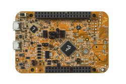
The FRDM-K22F is an ultra-low-cost development platform for Kinetis K Series K2x (K22F) MCUs built on ARM® Cortex™-M4 processor. Features include easy access to MCU I/O, battery-ready, low-power operation, a standard-based form factor with expansion board options and a built-in debug interface for flash programming and run-control. The FRDM-K22F is supported by a range of NXP and third-party development software.
Overview
The FRDM-K22F is an ultra-low-cost development platform for the latest Kinetis K22 MCUs. The FRDM-K22F hardware is form-factor compatible with the Arduino™ R3 pin layout, providing a broad range of expansion board options.

Important Notes
Please note that on this MCU in SPI Slave mode pins labeled MOSI behave as Slave Output and pins labeled MISO behave as Slave Input. The terms MOSI (Master Out Slave In) and MISO (Master In Slave Out) only apply to Master mode.
The FRDM-K22F is feature packed with a lot of peripherals to enable rapid prototyping, including a six-axis digital accelerometer and magnetometer to create full eCompass capabilities, a tri-colored LED, two user push-buttons for direct interaction and feedback, and connectivity options using onboard Ethernet port and headers for use with Bluetooth and 2.4 GHz radio add-on modules. The FRDM-K22F platform features OpenSDAv2, the NXP open source hardware embedded serial and debug adapter running an open source bootloader. This circuit offers several options for serial communication, flash programming, and run-control debugging. The FRDM-K22F is supported by a range of NXP and third-party development software.

The FRDM-K22F is fully supported in the mbed platform, so it gets access to the tools and SDK that provides experienced embedded developers with powerful and productive tools for building proof-of-concepts. The pinout above shows the commonly used interfaces and their locations. Note that all the numbered pins (PTXX) can also be used as DigitalIn and DigitalOut interfaces.
Features
- NXP K22F Kinetis MCU (MK22FN512VLH12)
- High performance ARM® Cortex™-M4 Core with FPU
- 120MHz, 128kB RAM, 512kB FLASH
- Crystal-less USB (Host/Device)
- SPI (2)
- I2C (2)
- I2S (1)
- UART (3)
- PWM (16)
- ADC (2x 16bit (w/ input mux))
- DAC (2x 12bit)
- GPIO (40)
- Analog Comparator (2x w/ 6bit DAC)
- FRDM-K22F Onboard Sensors
- FXOS8700CQ - 3-axis accelerometer and 3-axis magetometer
- Visible light sensor - ALS-PT19-315C/L177/TR8
- 2 user push buttons
- FRDM-K22F Optional Sensors
- microSD card slot over SPI
- header for RF module: nRF24L01+
- header for Bluetooth module: JY-MCU BT (V1.05 BT)
- Evalution Form factor
- 81mm x 53mm
- 5V USB or 4.5-9V supply
- Built-in USB drag 'n' drop FLASH programmer
- mbed HDK & SDK enabled
- Drag-n-drop programming
- USB Serial Port
- CMSIS-DAP
- Online development tools
- Easy to use C/C++ SDK
- Lots of published libraries and projects
Firmware
FirmwareUpdate
A new interface firmware image is necessary to mbed-enable NXP FRDM boards
Getting Started with mbed
1. Connect your microcontroller to a PC
Use the USB lead to connect your mbed to a PC. The status light will come on, indicating it has power. After a few seconds of activity, the PC will recognise the mbed Microcontroller as a standard USB drive.
 |  |
| Windows XP example | Mac OS X example |
2. Click the MBED.HTM link to get logged in
Go to the new USB Drive, and click MBED.HTM to open it in a web browser.
If you do not have an mbed account, choose "Signup", and create your mbed Account. Otherwise, log in with your normal username and password.
This will give you access to the website, tools, libraries and documentation.
PC Configuration
Your mbed Microcontroller can appear on your computer as a serial port. On Mac and Linux, this will happen by default. For Windows, you need to install a driver:
Windows
See Windows-serial-configuration for full details about setting up Windows for serial communication with your mbed Microcontroller
From a host PC to communicate with mbed you will need a terminal application. This allows the mbed Microcontroller to print to your PC screen, and for you to send characters back to your mbed.
- Terminals - Using Terminal applications to communicate between the Host PC and the mbed Micrcontroller
Some terminal programs (e.g. TeraTerm) list the available serial ports by name. However, if you do need to know the identity of the serial port so that you can attach a terminal or an application to it:
| Windows | Mac | Linux | ||||
| Find the identity of the COM port by opening ''Device Manager''. To do this navigate ''Start -> Control Panel -> System -> Hardware -> Device Manager''. | To find the device name under Mac OS X, use the command ''ls /dev/tty.usbmodem*'' | To find the device name under Linux, use the command ''ls /dev/ttyACM*'' | ||||
 |  |  |
Downloading A program
1. Save a program binary (.bin) to the FRDM Platform
Download the appropriate "Hello World!" binary:
- NXP FRDM-K22F: HelloWorld_K22F.bin
Note: the source code for this program will be seen in the next section.
Save the program binary file to your mbed Microcontroller Disk, just like you would with a normal USB disk. The Status LED will flash as the PC writes the file to the Microcontroller disk.

2. Press the Reset Button
When the Reset Button in pressed, the newest program on the mbed Microcontroller Disk will be loaded in to the microcontroller FLASH memory. The Status LED will flash as this happens.
When the program is has been loaded onto the microcontroller, it will then start it running.
3. Hello World!
The microcontroller is now running the program; flashing LED1 forever! If you reset the microcontroller, or disconnect and reconnect the power, the program will simply restart.
4. To download a different program
It is the newest program on the mbed Microcontroller that is run after reset. We can therefore download a new program or overwrite an existing one to update the program that will run.
Hello World!
Import programmbed_blinky
The example program for mbed pin-compatible platforms
Last commit 08 Apr 2019 by  Mbed
Mbed
Where Next
Follow the guide to creating your own programs using the online compiler
Technical Reference
Power
- USB powered or 4.5v - 9v on Vin pin
- Current (active): < _ _ _ mA
- Current (sleep): < _ _ _ mA
- 3.3v regulated output on VOUT to power peripherals
- 5.0v from USB available on 5v (only available when USB is connected unless extra regulator is added!)
- Digital IO pins are 3.3v, 4mA each, 400mA max total
Schematics
Data Sheets
- NXP K22 Data Sheet
- NXP K22 Reference Manual
- NXP K22 Errata Sheet
- ALS-PT19-315C/L177/TR8
- NXP FXOS8700CQ Data Sheet
Interface Firmware
You need to log in to post a discussion
Discussion topics

Questions
 Wei WU
 6 years, 6 months ago
Wei WU 6 years, 6 months ago
Wei WU 6 years, 6 months ago
To compile a program for this board using Mbed CLI, use k22f as the target name.
 Mbed Enabled
- Baseline
Mbed OS support
- Mbed OS 2
- Mbed OS 5.10
- Mbed OS 5.11
- Mbed OS 5.12
- Mbed OS 5.13
- Mbed OS 5.14
- Mbed OS 5.15
- Mbed OS 5.4
- Mbed OS 5.5
- Mbed OS 5.6
- Mbed OS 5.7
- Mbed OS 5.8
- Mbed OS 5.9
- Mbed OS 6.0
- Mbed OS 6.1
- Mbed OS 6.10
- Mbed OS 6.11
- Mbed OS 6.12
- Mbed OS 6.13
- Mbed OS 6.14
- Mbed OS 6.15
- Mbed OS 6.2
- Mbed OS 6.3
- Mbed OS 6.4
- Mbed OS 6.5
- Mbed OS 6.6
- Mbed OS 6.7
- Mbed OS 6.8
- Mbed OS 6.9
Example programs
CMSIS support
Find documentation, software examples and the CMSIS Board Support Pack.
FRDM-K22F on keil.arm.com