mbed compiler with LPC11U24 bare metal, no external crystal!

28 Aug 2012

Hey mbed people!

I am developing a PCB with the LPC11U24. According to the LPC11U24 datasheet, if high-speed USB connectivity is not needed, one can configure the chip to use the 12 MHz (+/- 0.12 MHz) Internal high-frequency RC oscillator (IRC) as a system clock, thereby eliminating the need for an external crystal on the PCB! This is very interesting, because it means with very few parts (and potentially using just the online compiler) some really cool stuff can be built!

So here’s the BIG question to the mbed people: Does the mbed online compiler support configuring the LPC11U24 to simply use the IRC as a system clock instead of the external crystal? If not, would it be possible to add some sort of compiler flag to signal the online compiler to do so?

From a hardware point of view, it appears it is simply a matter of grounding XTALIN and leaving XTALOUT floating.

Finally, perhaps it works right out of the box, but it isn’t clear to me if the LPC11U24 hardware automatically falls-back to the IRC if the external crystal if it not connected.

Many Many thanks to any insight that can be provided!

PS I am aware that I would have to load the firmware onto the chip using a tool such as flashmagic over UART since USB bootloading is not possible without an external crystal

28 Aug 2012

Hi Robbie,

Is this what you mean? (sorry if its still sideways) :

To make this work I had to get Dan and his team to make change to the online compiler so that the binary produced already has the vector table checksum inserted

In my example I am using the crystal that you're trying to design out, so I can't answer your big question from experience, but it seems plausible. We'd be unlikely to add this as a feature to the compiler, but it should be possible to do from the program.

The only word of warning I'd give it is to be careful, as you can make your mbed unresponsive. Here is how to recover if you do manage to brick your mbed : Unbricking your mbed

However, I can confirm that this is indeed the case :-)

Quote:

This is very interesting, because it means with very few parts (and potentially using just the online compiler) some really cool stuff can be built!

29 Aug 2012

Hey Chris, I really appreciate your reply. The awesome built-in USB bootloader and the video to prove it is very welcoming (I'm sure to many more than just myself). I was curious if the online compiler dealt with the vector location 7 (as per pg. 368 of the manual rev. 3), and you have confirmed this to be true! Great!

As you have demonstrated, it is relatively painless to get my *.bin file into the bare-bones LPC11U24 using the built-in USB bootloader so long as a crystal is attached to the LPC11U24 during the bootloading session (since this is required for the built-in bootloader's Mass Storage Device as per the LPC11U24 manual).

However, do you have any suggestion as to what code would be required to prevent/override the mbed-online compiler from configuring the LPC11U24 to use the crystal in the *.bin file that is generated? I realize if this were a full mbed, and not a bare-metal LPC11U24 as is in my case, bricking is a danger.

You mentioned it should be possible to configure the clock from within my user program... but if there is no crystal on my final product, I don't see how the execution will ever reach my main(), since I assume, by the time my main() function is called, the mbed libraries will have already configured the LPC11U24 chip to use the [non-existent] crystal.... thus freezing up execution. Does this make sense? Have I missed the way away around this problem or do I have to move away from the online compiler?

18 Sep 2012

What pins did you use to enable USB Boot Loader?

I have looked through LPC11U24 Datasheet, but cannot find info.

I want to use the 48 pin device in a new PCB i am about to start today.

Cheers

Ceri

18 Sep 2012

Hi Robbie,

Sorry, I have just spotted the lack of reply to your questions. I am pretty sure I typed one out at the time, not sure what happened.

You are of course right, with no crystal the program will not get as far as executing the user code that switches the clock source. I've seen it done in mbed program, but because the crystal is there, the program executes. I'll have to have a think about this, as it is bordering on the "special use case", i.e. how do we enable people to do this without confusing/inconveniencing those who just want to use mbed as-is.

I'll get back to you (this time in less than 20 days!)

Thanks, Chris

18 Sep 2012

Hi Ceri,

Its a little hidden in the "Programming Flash" section, under the ISP stuff. basically, as part of going into ISP mode, in P0.3 is sampled. If it is high the mass storage boot loader starts, if it is low the serial port boot loader starts.

For fun I have attached the PDF of the schematics, and the Eagle sch/brd for the little PCB from that video. It may or may not be useful!

Thanks, Chris

lpc11u24-bob.zip

19 Sep 2012

Chris, thanks again for the update.

Basically, here's my pitch:

1. Step one is to prototype like crazy with mbed. In my case an app that uses many pins, and no built-in USB

2. Once the prototype is ready... Deploy a custom PCB with the LPC11U24 chip and a *ridiculously low part count* since the 12mhz crystal and two 18pF caps could be omitted (in small quantities this saves nearly 50%)! I got a basic running app with only 2 bypass caps on the LQFP48 using the built in oscillator thanks to this helpful post which got me started :

Import programblinky

blinky example from NXP code bundle for LPC11Uxx. No mbed library used

The above blinky code does not use mbed libraries at all therefore I was able to configure the app to use the internal oscillator... BUT... for a real-world app, it means we'd have to start allllll over again since none of the basic mbed library functions would be at our disposal (a bad thing)!

Of course, if the mbed source code was open then it would be very easy to make our tweak... but I'm not sure your plans are with that, so in the meantime I'd like to suggest a cool way the LPC11U24 could be configured to use the internal oscillator without "hurting" anyone. It would require a small update to the online compiler, and perhaps the creation of a very basic page in the Handbook called "advanced compiler options":

Imagine a flag such as this at the top of the main code file in the online compiler:

// tell compiler to configure LPC11U24 for IRC clock source
#define MBED_COMPILER_FLAG_LPC11U24_USE_INTERNAL_OSCILLATOR 1

// and the business as usual
#include "mbed.h"

This [presently fictitious] flag could signal to the mbed compiler to configure the clock for the internal oscillator. Such an option could even perhaps pave the way for future configurations enhancements that cannot be set in user code (I actually can't think of any right now but I seem to remember some stuff from the forums).

/media/uploads/robodude/the-lpc-dream2.jpg

You could even have a built-in NOTICE in the compiler messages when the flag is spotted: "LPC11U24 clock configured for IRC (internal RC oscillator)! Proceed at your own risk!"

The LPC11U24 is a great low-cost chip with plenty of processing power for tons of embedded applications... The only downside of using the internal oscillator means no high-speed USB (including built-in USB bootloader as per the manual, which means traditional UART ISP applies). But for embedded applications, you could be some ridiculously awesome stuff with basically 1 chip and 2 bypass caps.

A picture is worth 1000 words:
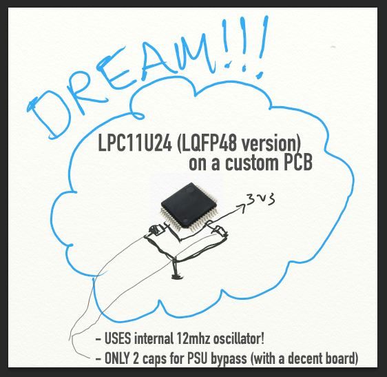
/media/uploads/robodude/the-lpc-dream.jpg

PS ok I'll spill the beans: Imagine driving 4 low-cost 8x8x3 RGB matrices (that's 768 individual leds) with full PWM colour, realtime communication, and awesome frame-rate... with only 1 LPC11U24, two bypass caps, a few source and sink drivers, and clever matrix programming.

19 Sep 2012

Hi Robbie,

Thanks for the last post. Like the pitch, especially that you've pitched the dream in TechniColour.

There are fixes possible in the short term, probably different ones in the longer term, so we'll have a think about how to proceed. WE'll be right back...

Thanks, Chris

20 Sep 2012

Hi Robbie,

As promised, here is a solution to the problem you are trying to overcome.

Patching functions and libraries

I have written it up as a notebook page so that it can become a bit of a reusable app note.

Hope this helps!

Thanks, Chris

21 Sep 2012

It Lives ...

bare metal LPC11U24:

USB connection,(3 resistors, 2 Caps., 1 FET)

4 LED's

3V3 Regulator,

two small switches.

Q: do I try with no crystal ?

Cheers

Ceri

21 Sep 2012

A: well it apears to work!

one caveat:

I used USB, with crystal to programm, Removed crystal,

Reset, ...

One flashing LED :)

Need to verify speed/frequency, but I think it is close.

If I get a chance later, then I will try programming with RS232 !!

Ceri

21 Sep 2012

Hi Ceri,

Using the IRC should be enough for low speed USB, which is what I assume the boot loader uses. If you want to do faster USB,then an proper crystal is required.

Thanks, Chris

21 Sep 2012

Hi Guys, I have only tested the chip crystal-free using UART-based ISP. For the USB-based flashing utility based on the mass-storage controller, the manual seems to say you need a crystal (from page 370 of the UM10462 LPC11UXX manual):

Quote:

The LPC11Uxx is enumerated as a Mass Storage Class (MSC) device to a PC or another embedded system. In order to connect via the USB interface, the LPC11Uxx must use the external crystal at a frequency of 12 MHz. The MSC device presents an easy integration with the PC’s Windows operating system.

Perhaps you'll get lucky and it will work without, or perhaps the manual is wrong :) Let us know if it works!

21 Sep 2012

Managed to program LPC11U48 (401) using:

USB Flash Disk (DFU) :)

Flash Magic, with lower baud rate NO CRYSTAL !!

hope this inspires you

Ceri

23 Sep 2012

Hello Ceri,

can You please write more about using DFU method? Do You need any software on PC?

24 Sep 2012

The very short answer. is no software,

Reset and ISP switch,

and one more pin on micro pulled Hi ( for DFU)

All you need to do is come out of reset with ISP low, and DFU Hi, you get a new drive in Windows,

delete the file, replace with. MBED file from compiler,

Normal reset...

all done.

Hope that explains it.

will try and post photo later .

Ceri

24 Sep 2012

Hey Ceri,

So you were able to have the LPC11U24 show up as a drive in windows, and there is no crystal on the board?

24 Sep 2012

Yes.

No.

with crystal, I had a drive for re-flashing ,

but with no crystal I needed flash magic.

must admit did not try because I am 98% sure you need crystal for DFU

Ceri

24 Sep 2012

OK cool... I was able to do exactly the same as you. UART/ISP (via flashmagic or similar) without crystal at 115200 bps (the max "official" supported baud although I got it up to 150000). With the crystal, the virtual usb-disk shows up in windows. Yes, you have to be careful about the VBUS pin, ISP, and reset. The order is important :)

24 Sep 2012

a fix for you might be to add a pad for X-in.

and squirt 12Mhz in from function generator or clock module.

that will keep your piece part price low, but no field DFU

Ceri

24 Sep 2012

Hello Ceri,

thank You for Your answer. I have idea of little board with USB connector to be USB RAW HID device with some digital I/O. My idea is use slide switch on side of board to select its operation - - > If I connect device (USB powered) with slide switch in one position device will act as USB RAW HID and will be processing program. But If I connect device with slide switch in second position device will boot up as USB DFU to get new firmware on.

I would like to ask You if this is possible with such slide switch because I would like to avoid ISP RST buttons combo on my board.

I am getting ideas from LPC11U1x/LPC1343 Cortex M0/M3 Microcontroller Breakout Board at http://github.com/Squonk42/USBug with PCB layout and such. In schematics is written "R3/R5 will cause the bootloader to boot into USB/MSC mode if USB is connected, and into UART/ISP mode otherwise".

So do I understand that if when I plug my dreamed board to USB port and VBUS pin is set high LPC11U1x will switch to DFU? And when I connect my board with VBUS pin low device will operate in normal mode and process code? I feel I will need to set high or low ISP pin and/or RST pin on power on too... Or am I missing something?

So biggest question is: Am i able to swith between DFU and normal program execution with just one slide switch or do I absolutely must accomodate ISP and RST switch too? Board will be only USB powered so my idea is that I reset board via unplugging board from USB.

I am sorry of my chaotic questions but I am not good in hw and components.

Thank You

24 Sep 2012

Just did a quick test,

DFU/USART pin set to USB, ISP Switch pressed down, Plugged in USB cable, (causing a reset, on power up)

Ha-Presto CRP Disabled drive with firmware.bin in it ..

Therfor: YES

you will be able to do this with just one switch/button

Just remember to put it back to HID after.

.. Recomend a press switch :)

Ceri

28 Sep 2012

Hello Ceri,

do You mean that when I press and hold button while connecting board to usb to get programmed and when connecting board without button being held board will run program and act as Raw HID? This is very clever!!!

But now I have big question. I want to order some parts but I am not about minimum parts I need to run LPC11u24 chip to get run with USB working.

I am designing my first little board based on http://github.com/Squonk42/USBug. But before ordering all smd stuff according to BOM of board I want to try some experiments with LPC11u24 and minimum through hole stuff.

So I am looking for any LQFP adapter to house micro and rest I want as through hole stuff to be able run some quick experiments on breadboard. I also have chosen 12 MHZ crystall.

In post above there are mentioned bypass caps but I am not sure about their values. Can anybody tell me minimum parts I will need to run quick tests?

28 Sep 2012

This is MY test board,

LPC11u64 12 Mhz crystal, with 12 or 18 pF caps (depends on crystal)

1*10nF decoupoling cap (far right)

3V3 regulator + 2*100nF Caps

4 0402 LED's

/media/uploads/ceri/_scaled_dsc_0670.jpg

Yes:

if you hold down ISP Button, puug in USB = Mass Storage,

just plug in USB = HID Device :)

Cari

28 Sep 2012

Thank You Ceri, this helps me very much. I am going to find and order such parts. Thanks again for very quick reply. I will post some news how I am going in future.

07 Oct 2012

Hello Ceri, I want to share my progress for own lpc11u24 board. I ordered lpc11u24 in LQFP48 package, LQFP48-100 pin adapter, 12 MHz crystal, 3v3 voltage regulator and caps as You mentoied.

I also ordered all equipment for soldering as mentoied here http://youtu.be/J5Sb21qbpEQ and followed instructions here http://youtu.be/b9FC9fAlfQE by EEVblog.

/media/uploads/llumpu/_scaled_07102012530.jpg

I must say that I had some little experience with soldering but not much. What I did not expect was so quick progress. I soldered this 0.5 mm pitch package so easy I could not believe.

I checked for bridged pins with multimeter to be sure.

/media/uploads/llumpu/_scaled_07102012533.jpg

Adapter I got was 1 layer board so I soldered all headers from other side and board sits on table chip facing down:o(

Also voltage regulator I received was too small to fit on breadboard so I power my board from mbed.

By datasheet I determined which pin equals on mbed and my 48 pin package and selected p20 and p22.

I wrote program to blink Leds attached to these pins. It was like a magic. After loading program to newly recognized "flash disk" and restarting board, leds started to blink!!!

I also tested HID example successfully.

I got working my own LPC11u24 chip for first attempt so I am pretty happy with it!!!

As I succesfully passed first stage, I plan to write notebook page following my progress in creating my dreamed USB HID board.

07 Oct 2012

Nice to see more peapole are gettint thair hands dirty :)

does this mean you are going to get a PCB made ?? a whole bunch of new chalinges.

Good work,

Ceri

07 Oct 2012

Yes, I want to get made PCBs I will design in next stage of project for me and my friend. My design will be based on project I mentoied earlier mainly for schematic and components placement but I will change rest to my needs. I hope this stage will be successfull too.

07 Oct 2012

Hi Guys, I am glad to see lots of people working with the 48-pin version of the LPC11U24. Indeed, it is really a simple setup! I just wanted to point out to those of you building PCBs of a potential mistake on the official mbed schematic. Since I don't want to double post, you can read my bug report here. It is not a very substantial bug, and your boards will most likely work anyway, but I'm still waiting to hear back from @mbed on this for their official recommendation.

18 Jan 2017

delete "mbed" inport "mbed-dev" modify include file .. file -> mbed.dev - targets - TARGET_LPC11UXX - device - system_LPC11Uxx.c about line 145-

  1. define CLOCK_SETUP 1
  2. define SYSOSCCTRL_Val 0x00000000 Reset: 0x000
  3. define WDTOSCCTRL_Val 0x00000000 Reset: 0x000
  4. define SYSPLLCTRL_Val 0x00000023 Reset: 0x000
  5. define SYSPLLCLKSEL_Val 0x00000000 originalsource 0x00000001
  6. define MAINCLKSEL_Val 0x00000000 originalsource 0x00000003
  7. define SYSAHBCLKDIV_Val 0x00000001 Reset: 0x001
  8. define USBPLLCTRL_Val 0x00000023 Reset: 0x000
  9. define USBPLLCLKSEL_Val 0x00000000 originalsource 0x00000001
  10. define USBCLKSEL_Val 0x00000000 Reset: 0x000
  11. define USBCLKDIV_Val 0x00000001 Reset: 0x001