Serial Interrupts
This is a simple demo project showing how to setup an interrupt driven serial port with buffering using the existing mbed Serial support without talking directly with UART hardware. There is also a MODSERIAL project that talks directly to UART hardware registers and it is probably more efficient time wise and easier to use, but it is a bit more difficult to understand all of the low level hardware code details. Also there is a new BufferedSerial project. Serial ports can transmit and receive data at the same time. RS-232 serial handshaking lines to start and stop the data flow are typically not used or connected, so using interrupts along with buffering of character data is typically required to avoid loss of characters at high baud rates on serial ports. UARTs have an internal FIFO buffer to hold perhaps 16 characters or so, but it is just not large enough. The other important advantage is that using interrupts saves processor time, since code does not spin in I/O wait loops constantly checking slowly changing I/O status bits.
Two circular buffers are used to hold serial data with an in and out pointer. One buffer is used for TX data buffering and one for RX data buffering. In is the location where new data is added to the buffer and out is the buffer location where data is removed. When in and out are incremented and reach the end of the buffer they wrap around using mod (i.e., %) buffer size. The buffer empty condition is in=out and the buffer full condition is (in + 1) % buffer size = out.
Using attach, you can specify the interrupt handler function for serial receive and serial transmit. In general, interrupt routines should not call any library functions unless you know that they are reentrant. Typically, they are not reentrant. Most hardware I/O devices cannot be in use in the main program and also used by an interrupt routine without problems. Mutual exclusion may also be needed on such hardware devices by disabling interrupts in the main program whenever the I/O device is being actively used.
Formatted IO using sprintf and sscanf
Getc and putc will work with interrupt routines, but in many cases formatted I/O using printf or scanf would be more desirable.
Printf() in its current version cannot currently be used with any serial interrupt routines that use getc. Even a printf to a different serial port such as USB that does not have an interrupt handler will lock up, if one serial port has interrupt code using getc. This is likely some reentrancy issue with the two functions. For buffering, sprintf needs to be used in any case. Fortunately, it is possible to use sprintf() to print to a buffer first and then copy the formatted data into the TX buffer using another function. In this code, the function is called send_line. Sscanf() is used in a similar manner with read_line in this short demo program.
Critical Sections using Enable and Disable Interrupts
When accessing and modifying global or shared data with more than one process (i.e., main and interrupt routine) mutual exclusion is needed to avoid errors due to data inconsistency. This can happen when switching back and forth between processes while a new global or shared variable value is being changed in a register and has not yet been written back to memory. With an OS, synchronization primitives would normally be used to solve this critical code section problem. On a single processor system with no OS, mutual exclusion for critical sections can be provided by disabling interrupts. In the case here, we only want to disable interrupts briefly from the UART on the serial port being used. The volatile keyword in C on variable declarations helps this problem somewhat by making operations on that variable atomic (i.e., non-interruptible), but does not solve all of the possible problems here with the buffer array. In the mbed compiler, interrupts can be disabled with __disable_irq(); and enabled with __enable_irq(); (i.e., prefix is two underscores). In the mbed C compiler, the functions NVIC_EnableIRQ() and NVIC_DisableIRQ() are used to disable and enable individual interrupts. In the demo code, UART1 interrupt hardware is used (i.e., UART1_IRQn). UART1 connects to p9 and p10. This ARM Cortex M3 textbook and the LPC1768 User Manual explain the UART and interrupt control hardware in more detail. LPC17xx.h contains interrupt assignments and names. There is even a book just on serial ports.
Running the Demo Code
The test program below sets up two interrupt routines (Rx,Tx) with two circular buffers. It is setup for a loopback test, and serial out must be tied back to serial in with a jumper wire from mbed p9 to p10. In an infinite loop, the main program increments a counter, prints out the counter in hex, decimal, and octal on three lines with sprint() and send_line. It then reads back three lines using sscanf and read_line. If there are any errors reading back data, led4 turns on and stays on. In the main program, while sending data led3 is on and while reading data led3 is off. Led1 and led2, indicate code activity in the two interrupt routines. So if all is well, led1, led2, and led3 are dimly lit and led4 is off.
Serial_Interrupt_Demo
#include "mbed.h"
// Serial TX & RX interrupt loopback test using formatted IO - sprintf and sscanf
// Connect TX to RX (p9 to p10)
// or can also use USB and type back in the number printed out in a terminal window
// Sends out ASCII numbers in a loop and reads them back
// If not the same number LED4 goes on
// LED1 and LED2 indicate RX and TX interrupt routine activity
// LED3 changing indicate main loop running


Serial device(p9, p10);  // tx, rx
// Can also use USB and type back in the number printed out in a terminal window
// Serial monitor_device(USBTX, USBRX);
DigitalOut led1(LED1);
DigitalOut led2(LED2);
DigitalOut led3(LED3);
DigitalOut led4(LED4);


void Tx_interrupt();
void Rx_interrupt();
void send_line();
void read_line();


// Circular buffers for serial TX and RX data - used by interrupt routines
const int buffer_size = 255;
// might need to increase buffer size for high baud rates
char tx_buffer[buffer_size+1];
char rx_buffer[buffer_size+1];
// Circular buffer pointers
// volatile makes read-modify-write atomic
volatile int tx_in=0;
volatile int tx_out=0;
volatile int rx_in=0;
volatile int rx_out=0;
// Line buffers for sprintf and sscanf
char tx_line[80];
char rx_line[80];


// main test program
int main() {
    int i=0;
    int rx_i=0;
    device.baud(9600);

// Setup a serial interrupt function to receive data
    device.attach(&Rx_interrupt, Serial::RxIrq);
// Setup a serial interrupt function to transmit data
    device.attach(&Tx_interrupt, Serial::TxIrq);

// Formatted IO test using send and receive serial interrupts
// with sprintf and sscanf
    while (1) {
// Loop to generate different test values - send value in hex, decimal, and octal and  then read back
        for (i=0; i<0xFFFF; i++) {
            led3=1;
// Print ASCII number to tx line buffer in hex
            sprintf(tx_line,"%x\r\n",i);
// Copy tx line buffer to large tx buffer for tx interrupt routine
            send_line();
// Print ASCII number to tx line buffer in decimal
            sprintf(tx_line,"%d\r\n",i);
// Copy tx line buffer to large tx buffer for tx interrupt routine
            send_line();
// Print ASCII number to tx line buffer in octal
            sprintf(tx_line,"%o\r\n",i);
// Copy tx line buffer to large tx buffer for tx interrupt routine
            send_line();
            led3=0;

// Read a line from the large rx buffer from rx interrupt routine
            read_line();
// Read ASCII number from rx line buffer
            sscanf(rx_line,"%x",&rx_i);
// Check that numbers are the same
            if (i != rx_i) led4=1;
// Read a line from the large rx buffer from rx interrupt routine
            read_line();
// Read ASCII number from rx line buffer
            sscanf(rx_line,"%d",&rx_i);
// Check that numbers are the same
            if (i != rx_i) led4=1;
// Read a line from the large rx buffer from rx interrupt routine
            read_line();
// Read ASCII number from rx line buffer
            sscanf(rx_line,"%o",&rx_i);
// Check that numbers are the same
            if (i != rx_i) led4=1;
        }
    }
}


// Copy tx line buffer to large tx buffer for tx interrupt routine
void send_line() {
    int i;
    char temp_char;
    bool empty;
    i = 0;
// Start Critical Section - don't interrupt while changing global buffer variables
    NVIC_DisableIRQ(UART1_IRQn);
    empty = (tx_in == tx_out);
    while ((i==0) || (tx_line[i-1] != '\n')) {
// Wait if buffer full
        if (((tx_in + 1) % buffer_size) == tx_out) {
// End Critical Section - need to let interrupt routine empty buffer by sending
            NVIC_EnableIRQ(UART1_IRQn);
            while (((tx_in + 1) % buffer_size) == tx_out) {
            }
// Start Critical Section - don't interrupt while changing global buffer variables
            NVIC_DisableIRQ(UART1_IRQn);
        }
        tx_buffer[tx_in] = tx_line[i];
        i++;
        tx_in = (tx_in + 1) % buffer_size;
    }
    if (device.writeable() && (empty)) {
        temp_char = tx_buffer[tx_out];
        tx_out = (tx_out + 1) % buffer_size;
// Send first character to start tx interrupts, if stopped
        device.putc(temp_char);
    }
// End Critical Section
    NVIC_EnableIRQ(UART1_IRQn);
    return;
}


// Read a line from the large rx buffer from rx interrupt routine
void read_line() {
    int i;
    i = 0;
// Start Critical Section - don't interrupt while changing global buffer variables
    NVIC_DisableIRQ(UART1_IRQn);
// Loop reading rx buffer characters until end of line character
    while ((i==0) || (rx_line[i-1] != '\r')) {
// Wait if buffer empty
        if (rx_in == rx_out) {
// End Critical Section - need to allow rx interrupt to get new characters for buffer
            NVIC_EnableIRQ(UART1_IRQn);
            while (rx_in == rx_out) {
            }
// Start Critical Section - don't interrupt while changing global buffer variables
            NVIC_DisableIRQ(UART1_IRQn);
        }
        rx_line[i] = rx_buffer[rx_out];
        i++;
        rx_out = (rx_out + 1) % buffer_size;
    }
// End Critical Section
    NVIC_EnableIRQ(UART1_IRQn);
    rx_line[i-1] = 0;
    return;
}


// Interupt Routine to read in data from serial port
void Rx_interrupt() {
    led1=1;
// Loop just in case more than one character is in UART's receive FIFO buffer
// Stop if buffer full
    while ((device.readable()) && (((rx_in + 1) % buffer_size) != rx_out)) {
        rx_buffer[rx_in] = device.getc();
// Uncomment to Echo to USB serial to watch data flow
//        monitor_device.putc(rx_buffer[rx_in]);
        rx_in = (rx_in + 1) % buffer_size;
    }
    led1=0;
    return;
}


// Interupt Routine to write out data to serial port
void Tx_interrupt() {
    led2=1;
// Loop to fill more than one character in UART's transmit FIFO buffer
// Stop if buffer empty
    while ((device.writeable()) && (tx_in != tx_out)) {
        device.putc(tx_buffer[tx_out]);
        tx_out = (tx_out + 1) % buffer_size;
    }
    led2=0;
    return;
}
Import programSerial_interrupts
A demo using serial interrupts with buffering in a loopback test

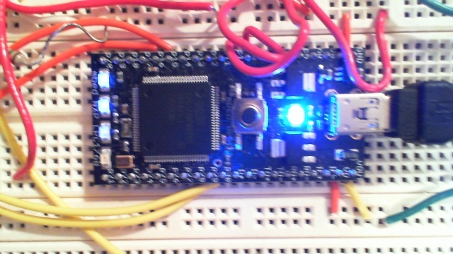
The mbed's four LEDs display activity from the serial interrupt demo code. The dim state shows that the code is constantly sending and receiving data in the main program (LED3) and that it is also spending some time in both of the serial interrupt routines (LED1 and LED2). LED4 is off indicating no errors in reading back thousands of data values using interrupts and buffering.
On many processors, the divide required for the mod (i.e., %) operation takes more execution time than the other basic integer operations. If the buffer size is restricted to a power of two, the mod operation could be replaced by a simple bitwise AND (i.e., &) operation that masks off the lower bits and it would have a faster execution time.
Tools and hardware to setup and debug serial connections
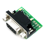
A voltage level conversion circuit or IC is required to connect mbed to an RS-232 serial port. The serial port on a PC uses RS-232 voltage levels +/-3 to +/-15V (i.e., not TTL 0-5V logic levels). This one from Sparkfun comes with the conversion circuit on a breakout board with the typical DB9 serial connector. It also has LEDs that indicate serial data flow.

| mbed | Sparkfun RS232 SMD adapter |
|---|---|
| 3.3V | Vcc |
| Gnd | Gnd |
| P9 - TX | RX |
| P10- RX | TX |
If you hook up a serial port and data is not flowing, a null modem serial cable or a null modem connector is often required so that TX is connected to RX, and RX is connected to TX at each end. Serial cables can be wired straight through or they may include the null modem signal swap and unfortunately they typically are not labeled. Here is a small DB9 mini null modem connector from Monoprice. If a null modem is required, you can't just swap the TX and RX pins to the mbed chip since the voltage level conversion circuits only work in one direction. Small gender changer adapters are also available when the cables are the wrong sex for the connector. Serial devices that work when the cable is plugged directly into the back of a PC will need both a null modem and a gender changer when used with mbed and the RS232 breakout boards. A single M/M DB9 null modem mini adapter could be used to minimize all of the connector clutter, if you can find one.

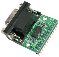
A few serial devices also require the optional hardware handshake signals for flow control. If you need to use handshaking, here is a serial breakout from Pololu that also includes the conversion circuits for the serial handshake lines http://www.pololu.com/catalog/product/126. The wiring table does not include connections that might be needed to RS-232 handshake lines, but the default no connection may be OK for some devices. Mbed's APIs do not support all hardware handshake options. In some, cases pulling the handshake line high or low can get a device talking that is waiting on a handshake signal to send data. Realterm shows the state of the handshake lines and they can also be forced high or low on the PC side to experiment with a device that needs a handshake (lower right in image of Realterm that follows in next section). A few devices even pull power off of a handshake line to power the serial device (see Magnetic card reader for such an example).

| mbed | Pololu RS232 adapter |
|---|---|
| VU=5v | VCC |
| GND | GND |
| RX(10) | TX |
| TX(9) | RX |
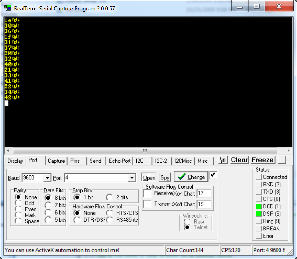
A terminal emulation program that runs on a PC is a handy way to test serial ports and code. Realterm as seen below includes more features to debug serial port hardware than most. It is seen running the demo code. It has a status display of the connector signals in the lower right. Data can be displayed in ASCII, or hex for binary data transmissions. It also displays non-printable ASCII control codes, so you can see exactly what data is being sent, even if it is a character that does not print. If your PC does not have a serial port, small RS232 serial to USB cables are available that can be used with a terminal emulation program. A special conversion IC is inside the cable and an OS device driver is typically required.

