LSM9DS1 IMU
A low-cost 3-axis accelerometer, 3-axis gyroscope, and 3-axis magnetometer IMU on a chip
Hello World
Import programLSM9DS1_Library
LSM9DS1 IMU Library by J Mar - Fixed typo on comment line 315 *.h file causing compile errors
Last commit 03 Feb 2016 by  jim hamblen
Library

Notes
NOTE
The library can successfully read the data values from the IMU, but the IMU's magnetometer readings will not be very accurate without some additional calibration. Most IMU applications also require some filtering.
Introduction
The LSM9DS1 is a versatile, motion-sensing system-in-a-chip. It houses a 3-axis accelerometer, 3-axis gyroscope, and 3-axis magnetometer – nine degrees of freedom (9DOF) in a single IC! Each sensor in the LSM9DS1 supports a wide range of…ranges: the accelerometer’s scale can be set to ± 2, 4, 8, or 16 g, the gyroscope supports ± 245, 500, and 2000 °/s, and the magnetometer has full-scale ranges of ± 2, 4, 12, or 16 gauss.
What are the various sensors are typically used for:
An accelerometer measures acceleration minus gravity. If the device is not moving, an accelerometer can be used to measure tilt from vertical, roll and pitch. Yaw cannot be measured.
An accelerometer with a magnetometer can be used as a 3D electronic compass. Nearby magnetic objects can effect accuracy of a magnetometer and calibration may be required for accuracy.
An accelerometer with a gyroscope is called and IMU and it can measure rotation in 3D space, but it has no global frame of reference since it cannot sense magnetic north. Computation of yaw is still not supported.
An Accelerometer plus Magnetometer plus Gyroscope (also called MARG) allows tracking of orientation, gravity, and linear acceleration. The magnetometer allows it to detect magnetic headings. An advanced filtering technique is typically required for accuracy. Kalman filters are optimal, but they require quite a few computations and heavy filtering can delay the output response, so other simpler filters are sometimes used.
An attitude and heading reference system (AHRS) consists of sensors (triple axis gyro, accelerometer, and magnetometer) that are used to provide data to compute the attitude information for aircraft, including roll, pitch and yaw angles.
An Inertial Navigation System may also add a GPS receiver to determine geographic location. Since gyro readings are integrated to obtain orientation and accelerometer readings are integrated to obtain position, the accuracy will tend to drift off over time because of measurement errors. A magnetometer can help correct long term gyro drift, and a GPS can help correct long term position drift. Unfortunately, GPS rarely works inside large buildings.
Most new software uses the open source Mahoney and Magwick filter code. Mahoney and Magwick filters use Quarternions (they are like complex numbers, but in higher dimensions) Kalman filters require more extensive matrix operations that can slow down things on a microcontroller. These filters can also estimate the gravity vector and subtract it to sense linear motion on the accelerometer. For more information, see Simple and Effective Magnetometer Calibration and Affordable 9 DoF Sensor Fusion
Overview
The LSM9DS1 can measure three key properties of movement – angular velocity, acceleration, and heading.
The LSM9DS1 measures each of these movement properties in three dimensions. That means it produces nine pieces of data: acceleration in x/y/z, angular rotation in x/y/z, and magnetic force in x/y/z.

SPI or I2C
In addition to being able to measure a wide variety of movement vectors, the LSM9DS1 is also multi-featured on the communication interface end. It supports both SPI and I2C.
The Serial Data Out (SDO) pin for example, does just that for SPI mode, but if you’re using the device over I2C it becomes an address selector. The chip select (CS_M and CS_AG) pins activate SPI mode when low, but if they’re pulled high the device assumes I2C communication.
Pinout

The LSM9DS1 allows for either an SPI or I2C interface
SPI
| Pin Label | Pin Function | Notes |
|---|---|---|
| DEN | Gyroscope Data Enable | Mostly unknown. The LSM9DS1 datasheet doesn't have much to say about this pin. |
| INT2 | Accel/Gyro Interrupt 2 | INT1 and INT2 are programmable interrupts for the accelerometer and gyroscope. They can be set to alert on over/under thresholds, data ready, or FIFO overruns. |
| INT1 | Accel/Gyro Interrupt 1 | Same as above |
| INTM | Magnetometer Interrupt | A programmable interrupt for the magnetometer. Can be set to alert on over-under thresholds. |
| RDY | Magnetometer Data Ready | An interrupt indicating new magnetometer data is available. Non-programmable. |
| CS M | Magnetometer Chip Select | This pin selects between I2C and SPI on the magnetometer. Keep it HIGH for I2C, or use it as an (active-low) chip select for SPI. HIGH (1): SPI idle mode / I2C enabled. LOW (0): SPI enabled / I2C disabled. |
| CS AG | Accel/Gyro Chip Select | This pin selects between I2C and SPI on the accel/gyro. Keep it HIGH for I2C, or use it as an (active-low) chip select for SPI. HIGH (1): SPI idle mode / I2C enabled LOW (0): SPI enabled / I2C disabled. |
| SDO M | SPI: Magnetometer MISO I2C: Magnetometer Address Select | In SPI mode, this is the magnetometer data output (SDO_M). In I2C mode, this selects the LSb of the I2C address (SA0_M) |
| SDO AG | SPI: Accel/Gyro MISO I2C: Accel/Gryo Address Select | In SPI mode, this is the accel/gryo data output (SDO_AG). In I2C mode, this selects the LSb of the I2C address (SA0_AG) |
I2C
| Pin Label | Pin Function | Notes |
|---|---|---|
| GND | Ground | 0V Voltage |
| VDD | Power Supply | Supply voltage to the chip. Should be regulated between 2.4V and 3.6V. |
| SDA | SPI: MOSI I2C: Serial Data | SPI: Device data in (MOSI) I2C: Serial data (bi-directional) |
| SCL | Serial Clock | I2C and SPI serial clock. |
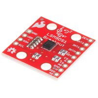
THIS IMAGE SHOWS I2C WIRING

How to Wire the Breakout to the Mbed
I2C
| Pin on Breakout | Pin on Mbed |
|---|---|
| GND | GND |
| VDD | Vout |
| SDA | p9 (SDA) |
| SCL | p10 (SCL) |
SPI
| Pin on Breakout | Pin on Mbed |
|---|---|
| GND | GND |
| VDD | Vout |
| SDA | p11 (MOSI) |
| SCL | p13 (SCLK) |
| CSAG | Any DigitalOut |
| CSM | Any DigitalOut |
| SDOM | p12 (MISO) |
API
Basic constructor and functions
/**
*Constructor for I2C
**/
LSM9DS1(PinName sda, PinName scl, uint8_t xgAddr, uint8_t mAddr);

/**
*Initialize the gyro, accelerometer, and magnetometer.
*This will set up the scale and output rate of each sensor.
**/
uint16_t begin();

/**
*Read the gyroscope output registers.
*This function will read all six gyroscope output registers.
*The readings are stored in the class' gx, gy, and gz variables. Read
*those _after_ calling readGyro().
**/
void readGyro();

/**
*Read the accelerometer output registers.
*This function will read all six accelerometer output registers.
*The readings are stored in the class' ax, ay, and az variables. Read
*those _after_ calling readAccel().
**/
void readAccel();

/**
*Read the magnetometer output registers.
*This function will read all six magnetometer output registers.
*The readings are stored in the class' mx, my, and mz variables. Read
*those _after_ calling readMag().
**/
void readMag();

/**
*Convert from RAW signed 16-bit value to degrees per second
*This function reads in a signed 16-bit value and returns the scaled
*DPS. This function relies on gScale and gRes being correct.
*Input: A signed 16-bit raw reading from the gyroscope.
**/
float calcGyro(int16_t gyro);

/**
*Convert from RAW signed 16-bit value to gravity (g's).
*This function reads in a signed 16-bit value and returns the scaled
*g's. This function relies on aScale and aRes being correct.
*Input: A signed 16-bit raw reading from the accelerometer.
**/
float calcAccel(int16_t accel);

/**
*Convert from RAW signed 16-bit value to Gauss (Gs)
*This function reads in a signed 16-bit value and returns the scaled
*Gs. This function relies on mScale and mRes being correct.
*Input: A signed 16-bit raw reading from the magnetometer.
**/
float calcMag(int16_t mag);
Code
Sample Program to use IMU through I2C printing to Serial COM
#include "LSM9DS1.h"

DigitalOut myled(LED1);
Serial pc(USBTX, USBRX);

int main() {
    LSM9DS1 imu(p9, p10, 0xD6, 0x3C);
    imu.begin();
    if (!imu.begin()) {
        pc.printf("Failed to communicate with LSM9DS1.\n");
    }
    imu.calibrate();
    while(1) {
        imu.readTemp();
        imu.readMag();
        imu.readGyro();

        pc.printf("gyro: %d %d %d\n\r", imu.gx, imu.gy, imu.gz);
        pc.printf("accel: %d %d %d\n\r", imu.ax, imu.ay, imu.az);
        pc.printf("mag: %d %d %d\n\n\r", imu.mx, imu.my, imu.mz);
        wait(1);
    }
}
Demo
More Information
Link to Sparkfun Guide for Breakout Hookup
Implementing a Tilt-Compensated eCompass using Accelerometer and Magnetometer Sensors
Calibrating an eCompass in the Presence of Hard- and Soft-Iron Interference
Additional IMU sensor fusion background information is available in Freescale (now NXP) Application Notes AN5016-AN5023 and several others
Here is some early experimental code that tries to auto calibrate the magnetometer for more accurate heading info:
Import programLSM9DS1_Demo_wCal
An Experimental IMU demo with some initial mag calibration code.
Last commit 03 Feb 2016 by jim hamblen
This code uses P28 and P27 for the I2C pins and not p9 and p10. The IMU must be rotated when prompted at startup for calibration. It uses the existing library code and most of the changes are found in main.cpp and the libraries calibration routines. It prints a bit more data and scales it into floating point values with standard units.

Data from IMU demo with calibration
There is also an student IMU project for the similar LSM9DS0 with a library that contains the Quarternion-based filter code that could likely be adapted for the newer LSM9DS1.
If you just import the library code and do not import a complete demo program, don't forget to setup a serial port for pc.printf outputs using Serial pc(USBTX,USBRX); or whichever serial port is being used on your mbed. Without this, a confusing fatal compile error "Cannot find argument 'os_cb_sections' ". may occur in some new versions of the mbed compiler.
You need to log in to post a discussion
Discussion topics
| Topic | Replies | Last post |
|---|---|---|
| New Lower Cost IMU board now available from Sparkfun | 0 |
26 Aug 2016
by
jim hamblen
|
Questions


Tested boards
