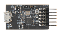
IN11 | Interface for SDT Board
Interface for SDT51822B, SDT52832B and SDT64B
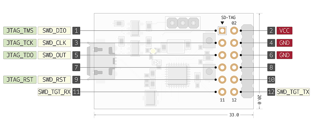
Pinout
Notes

1. Interface
The Interface programs and debugs SDT Board. An Interface is connected to SDT Board via the DAP Station and is powered by a PC through a USB cable. It is important that you use the right Interface for your Target MCU, since there are designated Target MCUs that are compatible with a certain Interface. IN11 is Interface for SDT51822B, SDT52832B and SDT64B.
2. DAPLink Interface Firmware
This programming process uses the Arm Mbed DAPLink to drive the Interface. The following functions
are provided.
1) Drag-and-drop Programming (MSC)
The SDT board is connected to the computer and drag-and-drop programming can be performed on
the flash of the SDT board.
2) Virtual Serial Port (CDC)
Serial connection from the SDT board to PC. The code written by the PC goes into the Interface and
SDT board.
3) CMSIS-DAP Based Debugging (HID)
This is a compatible feature when you want to see detailed events that occur on the SDT board and
Interface with an advanced debugger such as Keil or GDB.
3. DAPLink Programming Mode
DAPLink has two programming modes.
First, you can write to the Interface flash to update the firmware of the Interface. It’s called bootloader
mode. We recommend that you never update to an unverified version. It may cause serious problems.
Second, you can write to the memory of the SDT Board for programming. You can debug the SDT Board
using this mode.
4. How to connect Interface with SDT Board and DAP Station

- Prepare the Interface suitable for the SDT Board.

- Connect SDT Board to DAP Station.
- Use SD-TAG to connect Interface to DAP Station.

- Connect PC to Interface using Micro B-Type USB.
- Supply power to SDT Board using DAP Station’s Micro B-Type USB Connector.
- Use the online compiler on the Arm Mbed homepage or CLI to program and compile.
- Move the compiled file (.bin or .hex) into the DAPLink drive.
- For efficient connection, the SD-TAG of the DAP Station and SD-TAG Pin of the IN11 is
symmetrically positioned.
- The IN11 uses JTAG_TDO pin to serve as SWO.
- The IN11 supports SWD and UART communication for programming and debugging. It does not
support JTAG.
5. How to download a firmware of IN11
When you connect a new Interface, it will appear on your disk drive as “CRP Disabled.
In order to program the IN11:
- Open “CRP Disabled” drive, and delete “firmware.bin” file
- Download required image from the IN11 Page.

- Copy, or drag-and-drop “.bin file” to “CRP Disabled” drive.
- On Linux/Mac, use command: dd if={new_firmware.bin} of={firmware.bin} conv=notrunc
- Unplug IN11 and plug it back in.
- It will now appear on your disk drive as “DAPLink”
- You can re-program IN11 multiple times by disconnecting power, and then reconnecting power
with the RST button held down. Then, the Interface will appear as “CRP Disabled” drive, allowing
you to repeat the above steps.
#Sigma Delta Technologies
See also
Click the below link to buy IN11
- Product Link
You need to log in to post a discussion