NXP FRDM-34931-EVB Brushed-DC Motor-Control using FRDM-K64F
The FRDM-34931-EVB board is an evaluation environment for the MC33931, MC34931 and MC34931S, which works with Graphical User Interface available on NXP website to control a brushed DC motor using FRDM-K64F board
Hello World
Import programBrushed DC Motor Control using X-FRDM-34931SEVM and FRDM-K64F
MCU Code for FRDM-K64F which works with Graphical User Interface available on Freescale website to control a brushed DC motor using X-FRDM-34931SEVM. The code enables controlling the PWM frequency, duty cycle, enabling/disabling while monitoring status flag pin for undervoltge, short circuit and over-temperature events as well as real time load current for implementing advanced diagnostics.
Last commit 28 Dec 2015 by ![]() Freescale
Freescale
Library
Import programBrushed DC Motor Control using X-FRDM-34931SEVM and FRDM-K64F
MCU Code for FRDM-K64F which works with Graphical User Interface available on Freescale website to control a brushed DC motor using X-FRDM-34931SEVM. The code enables controlling the PWM frequency, duty cycle, enabling/disabling while monitoring status flag pin for undervoltge, short circuit and over-temperature events as well as real time load current for implementing advanced diagnostics.
Last commit 28 Dec 2015 by ![]() Freescale
Freescale
Pinout
Notes
GUI control tool
The sample code for FRDM-34931S-EVB works with FRDM-K64F and is controled by a dedicated GUI tool.
Download the "GUI Brushed DC for FRDM-34931S-EVB" from NXP Website.
FRDM-K64F Description and Pinout
The Flagship FRDM-K64F has been designed by NXP in collaboration with mbed for prototyping all sorts of devices, especially those requiring the size and price point offered by Cortex-M4®. It is packaged as a development board with connectors to break out to strip board and breadboard, and includes a built-in USB FLASH programmer. It's based on the NXP K64F, with a 32-bit ARM Cortex-M4F core running at 120MHz. It includes 1MB FLASH, 256KB RAM and lots of interfaces including Ethernet, SPI, I2C, ADC, DAC, PWM, UART and other I/O interfaces.

Firmware Update
FirmwareUpdate
A new interface firmware image is necessary to mbed-enable NXP FRDM boards
Connecting the Hardware
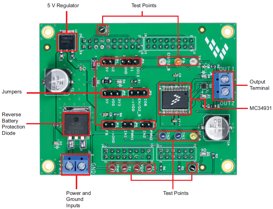
The FRDM-34931S-EVB shield consists of an H-Bridge, a parallel interface, power conditioning circuitry, and a set of two Input Select jumpers. All +5.0 V VDD power required by the board is obtained via the parallel interface.
WARNING
Damage to the board
To avoid damaging the board, the following restrictions must be observed:
- The motor supply voltage (VPWR) must be at least 5.0 V, but must not exceed 40 V.
- The peak operating current of the load must not exceed 5.0 A.
- Connect the FRDM-34931S-EVB to the FRDM-K64F
- With the power switched off, attach the DC power supply to the VPWR and GND screw connector terminals on the evaluation board (J5 in figure below).
- Attach one set of coils of the brushed motor to the OUT 1 and OUT 2 screw connector terminals on the evaluation board (J6 in Figure below).

Figure below illustrates the hardware configuration.

Generate the Program firmware and flash the FRDM-K64F Board
The microcode provides the firmware interface between the MC34931S device, the Freedom boards and the GUI.
The procedure is as follows:
- Connect the USB cable between your PC and the OpenSDA USB port on the FRDM-K64F board.
- Go to https://developer.mbed.org/teams/Freescale/code/Brushed-DC-Motor-Control-using-X-FRDM-34/ and click on the “Import this Program” tab
- If it is not already done, log into your mbed account. (If you do not have an mbed account, you must create one) and click on “Import this program” again.
- The mbed compiler opens the Import Program window. Click on “Import”
- When the import completes. Open the “main.cpp” item in the Project from the left panel
- The source code for main.cpp appears in the code editor. Click on the “Compile” button to compile the main.cpp source code.
- If the compilation ends successfully, a binary file will be automatically downloaded into the download folder of your web browser.
- Drag and drop this file to the mbed drive from your file explorer.
- Wait until copy completed and press the reset button to launch the program.
Using the Graphical User Interface(GUI)
After Installing the ""GUI Brushed DC for FRDM-34931S-EVB" from the link above, do the following:
- Disconnect the USB cable from the OpenSDA_USB port from the FRDM-K64F
- Reconnect the USB cable to the K64F_USB port from the FRDM-K64F
- Wait for the HID new peripheral to be properly enumerated by Microsoft Windows
- Launch the GUI Brushed DC FRDM-34931S-EVB tool
- Make sure the GUI recognizes the FRDM-K64F. Check the USB connection in the upper left corner of the GUI. The hex Vendor ID value should display as 0x15A2 and the Part ID value should display as 0x138. If these value do not appear, the GUI has failed to establish a connection with the FRDM-K64F. You may need to disconnect and reconnect the USB cable to the K64F_USB port of the FRDM-K64F board. If the connection still fails, press the reset button on the FRDM-K64F board.
- Click the “Enable Target” checkbox on the GUI screen. The Target parameter on the GUI screen should change from “DISABLED” to “ENABLED.”
- Enable D1 and EN/D2_B, and select Direction and Braking as desired and adjust the PWM Frequency and Duty Cycle to meet your requirements.
- Click the “Run” button to run the motor. Notice that some options of the GUI are disabled while the motor is running. To make changes, click the “Stop” button on the GUI, make the desired changes, and then click “Run” on the GUI to continue.
- When finished, de-select the “Enable Target” button on the GUI, and click the “Quit” button. Turn off DC power supply and remove the USB cable.
The GUI is shown in Figure below. The hex address numbers at the top are loaded with the vendor ID for NXP (0x15A2), and the part ID (0x138). The left side panel displays these numbers only if the PC is communicating with the FRDM-64F via the USB interface.

Forward with High-side Re-circulation
Configuration
- D1: Enable
- EN/D2_B: Enable
- Direction: Forward
- Braking: High-side

Forward with Low-side Re-circulation
Configuration
- D1: Enable
- EN/D2_B: Enable
- Direction: Forward
- Braking: Low-side

Reverse with High-side Re-circulation
Configuration
- D1: Enable
- EN/D2_B: Enable
- Direction: Reverse
- Braking: High-side

Reverse with Low-side Re-circulation
Configuration
- D1: Enable
- EN/D2_B: Enable
- Direction: Reverse
- Braking: Low-side

Direction Control with High-side vs. Low-side Recirculation
H-Bridge Operation Logic
The logic table below explains the H-Bridge motor control using the High-side / Low-side recirculation

Technical Doc
FRDM-34931S-EVB Board
MC34931S driver IC
Software Materials
FRDM-K64F Interface Firmware / OpenSDA Application
FRDM-34931S-EVB control software
Where to buy