NeoPixel LED chain using high speed SPI
NeoPixels are individually addressable RGB LEDs combined with constant current controllers, which can be used individually or chained into longer strings. In this demo we are using Adafruit NeoPixel Diffused 8mm Through-Hole LEDs but the same principles can be used for other NeoPixel packages.
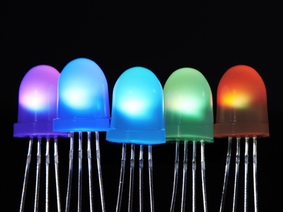 Adafruit NeoPixel Diffused 8mm Through-Hole LEDs
Wiring
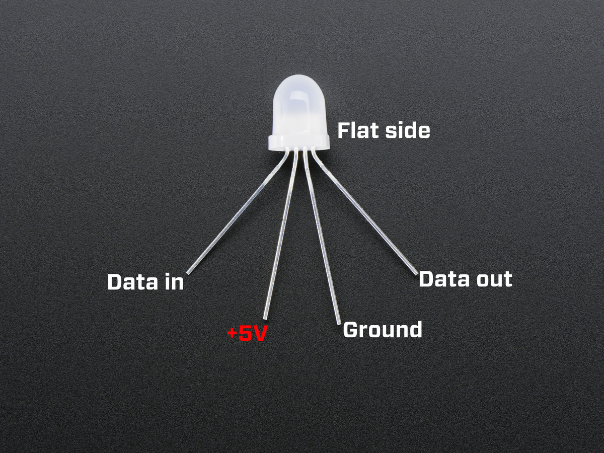
![]()
The through-hole NeoPixel variety has 4 legs: 5V, Ground, DataIn, and DataOut. In contrast to regular LEDs, NeoPixels require a microcontroller such as the mbed to program them and set their colors. The DataIn leg of one NeoPixel can be connected to the DataOut leg of another NeoPixel in order to create a chain of NeoPixels of any length.
Using suggestions from the best practices section of the Adafruit NeoPixel Uberguide, a large capacitor was place in parallel with the pixel chain and resistor was place in series between the mbed SPI mosi pin and the first pixel.
Other Wiring Notes
- Each NeoPixel can draw up to 60mA from the power supply. The mbed can support 5V/500mA through VU, so only small chains can be supported by an mbed plugged into USB.
- When powering the NeoPixels with a separate power supply, make sure that the NeoPixels are powered before the mbed.
- Although we managed to do the demo without changing the signal level coming from the mbed, technically NeoPixel requires a 5V data signal. So if you are experiencing some issues, this may be the reason. This can be remedied by using a logic level shifter, such as a 74AHCT125 - Quad Level-Shifter (3V to 5V).
RGB Color Fields
For most NeoPixel varieties the bitstream of data for each pixel should be in green, red, blue (GRB) order with the most-significant bit issued first. However, for the NeoPixel 8mm through-hole that we are using, the bitstream is red, green, blue order (RGB).

The color is set through a unique timing, PWM protocol to control brightness. The red, green, or blue brightness can be set, where 0 is the dimmest (off) and 255 is the maximum brightness. This protocol works by encoding 1s and 0s into a long or short HI pulse. A digital 1 is encoded as a long HI pulse, and a 0 is encoded as a short HI pulse. The device resets if the DataIn line is held LO for more than 50 µs.
When the device is reset, the NeoPixel reads the first 24 bits of received data from its DataIn line into an internal buffer. These first 24 bits are the GRB (green: red: blue) values (8 bits: 8 bits: 8 bits) for the first NeoPixel.
Any consecutive data bits received after the first 24 go through internal wave reshaping through the NeoPixel’s own signal reshaping circuit. The data is then sent out through the DataOut line and sent to the next NeoPixel in the chain, which will also separate the first 24 bits of the data into its internal buffer and pass along the rest of the bits.
During the following reset cycle, each NeoPixel writes the 24 bits that are in its internal buffer to its PWM controller and begins to shine the specified GRB value.
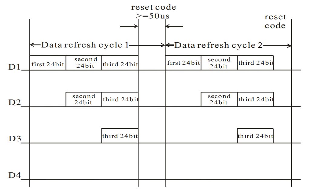
Timing
In the data sheet, the manufacturer lists the data transfer times for the encoding scheme. These are the lengths of time for the HI pulses in order to encode digital 1 or 0.
Timing Table from Datasheet

However, as discovered and outlined in Tim's Timing Blog, the actual timing and tolerances are different than the timing given by the datasheet.
Timing Table from Tim's Blog
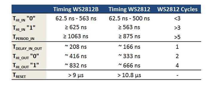
Notes from the Table
- The delay between any HI pulse entering the device through DataIn and exiting through DataOut is 166 ns.
- A HI pulse that encodes ‘0’ should be between 62.5 ns and 500 ns.
- A HI pulse that encodes ‘1’ should be greater or equal than 563 ns.
- The total input data transfer time should be greater than 875 ns.
- Internal wave reshaping in the circuit changes the output wavelength for a ‘0’ HI pulse to 333 ns and a ‘1’ HI pulse to 666 ns.
- The minimum time to reset (or minimum time that DataIn is held low) is about 10.8 µs, much less than the 50 µs reset time specified on the data sheet.
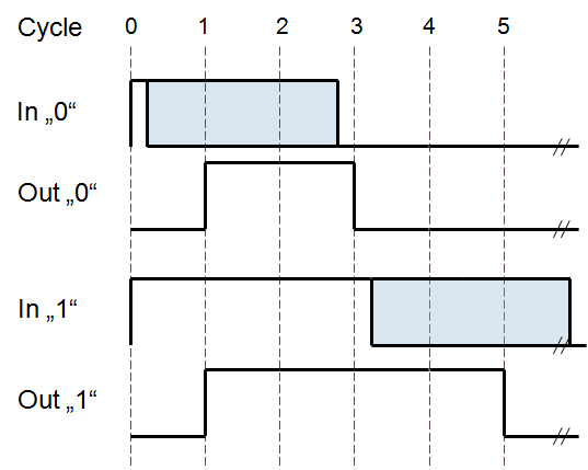
The blog also describes how NeoPixels contain a state machine which samples the input twice per bit. So, the state machine waits for a rising edge to sample the input. Then, after two cycles, the input is sampled again. If the voltage is low at this point, a ‘0’ is read, and if it is still high, a ‘1’ is read. At this point, the values are either loaded into the internal buffer/shift register or output with a 2 or 4 cycle HI pulse on the DataOut line.
NeoPixel Array Library
Import library
| Pixel | Represent the value of a single pixel |
| PixelArray | Control an array or chain of NeoPixel-compatible RGB LEDs |
The code and library are intended to control a chain of NeoPixels. Since the NeoPixel strict timing protocol is not supported by standard microcontrollers, the mbed will have to emulate this communication through software timed I/O toggling, or bit-banging.However, the library and code shown in this cookbook page uses the SPI peripheral instead.
The main advantages of using an SPI interface versus bit-banging is that SPI allows the mbed to service interrupts and the like without disrupting the signal, given that the interrupts aren’t too long. The code uses a special form of SPI called BurstSPI which sends SPI data without reading it back. This allows for higher speeds than the regular SPI library. This is useful for high frequencies, such as the 800 kHz data rate needed for the NeoPixels.
In order to control the NeoPixels, three different files are used: NeoPixel.h, NeoPixel.cpp, and main.cpp. The first step in configuring the NeoPixels is to edit the NeoPixel.h code. The code makes much use of a class called PixelArray which is found in line 95 of neopixel.h.
In line 103, the PixelArray class is defined with three parameters. The second parameter, byte_order, controls the order in which the color data bytes are sent to the NeoPixel. As explained above, the through-hole variety of NeoPixels runs on an RGB byte order. Therefore, the byte_order parameter should be set to
byte_order = BYTE_ORDER_RGB instead of BYTE_ORDER_GRB
Note
SPI peripherals will tend to leave the output pin ('MOSI') floating after a packet is sent. This will confuse the connected pixels, which expect the line to be driven low when idle. One way to fix this is to add a 10k resistor between 'MOSI' and ground so that it drops to '0' when not driven. Another method is to enable the on-chip pull-down resistor on the output pin. However, the mbed API only exposes this function through the DigitalIn and DigitalInOut classes. If you want to use the on-chip pull-down, you'll have to temporarily connect a DigitalIn peripheral _before_ creating instantiating the PixelArray.
The first parameter of the PixelArray class simply lists the SPI MOSI pin. This pin must be one of the two MOSI SPI pins on the mbed. In the main.cpp code, this pin is defined as p5. The third parameter specifies the data rate which should stay as 800 kHz for the NeoPixels.
The second step in controlling a through-hole NeoPixel chain is to specify the pattern and behavior that the NeoPixels should have. This is done by using the update function from the PixelArray class.
Two Methods for Updating LED colors
Using a pixel generator
This is specified in line 7 through 13 of the main.cpp code, in line 122 to 144 of neopixel.h, and in line 117 to 125 of neopixel.cpp. As explained in the comments of neopixel.h, the neopixels can be updated using a callback function to generate the value for each pixel.
The update method is good in the following situations:
- You have a lot of pixels to drive and don’t have enough RAM to buffer them all.
- You want to display a frame pattern that can be generated procedurally without intensive processing.
The generator is a callback function which is called to generate a value for each pixel on demand. This function must be fairly fast: if it takes more than 8-9µs, the interface will reset and the display corrupted. This is practically done by designing a generator in the main.cpp code. Inside neopixel.cpp, around line 131, the update function enters into a loop and creates an instance of the Pixel structure which contains 3 color fields: red, blue, and green. The loop runs for the number of iterations specified by the parameter, length. Length is the number of NeoPixels in the chain. It then calls the generator function which is defined in main.cpp. The generator function accesses the color fields in the instance of the Pixel structure and updates it as specified by the programmer. It then returns to the loop and sends the pixel data to the NeoPixel. It repeats this several times to create any pattern. See the helloworld example below.
NeoPixel Demo Buffer Using Pixel Generator
Import program
00001 #include "mbed.h"
00002 #include "neopixel.h"
00003
00004 // This must be an SPI MOSI pin.
00005 #define DATA_PIN p5
00006
00007 void generate(neopixel::Pixel * out, uint32_t index, uintptr_t extra)
00008 {
00009     uint32_t brightness = (index + extra) >> 3;
00010     out->red   = ((index + extra) & 0x1) ? brightness : 0;
00011     out->green = ((index + extra) & 0x2) ? brightness : 0;
00012     out->blue  = ((index + extra) & 0x4) ? brightness : 0;
00013 }
00014
00015 int main()
00016 {
00017     // Create a temporary DigitalIn so we can configure the pull-down resistor.
00018     // (The mbed API doesn't provide any other way to do this.)
00019     // An alternative is to connect an external pull-down resistor.
00020     DigitalIn(DATA_PIN, PullDown);
00021
00022     // The pixel array control class.
00023     neopixel::PixelArray array(DATA_PIN);
00024
00025     uint32_t offset = 0;
00026     while (1) {
00027         array.update(generate, 100, offset++);
00028         wait_ms(250);
00029     }
00030 }
Import programNeoPixel Demo
Demo application for Adafruit NeoPixels.
Using a C++ array or buffer of Pixel structures
The update function that uses an array of Pixel structures is defined in line 108 of neopixel.cpp.
This method is good for:
- One wants to make incremental changes to a fixed frame pattern
- The frame is hard (or impossible) to generate procedurally.
- The frame requires a lot of time to generate.
This update function takes the buffer or array of type Pixel as an argument along with the length of the buffer. Each element in the array represents one NeoPixel in the pixel chain; therefore, length specifies the number of NeoPixels in the array.
Buffer[0] is written to the pixel nearest the mbed.
Buffer[length-1] is written to the pixel furthest from the mbed.
This method is used by declaring an array of a defined length of pixels inside the main.cpp program. The array along with the length is passed to the array.update function.
Inside neopixel.cpp around line 180, one can manually set each color value of the elements in the array. Finally, a loop iterates through each structure in the array and sends the data to the NeoPixel. See the helloworld example below.
NeoPixel Demo Buffer Using C++ Array or Buffer
Repository: NeoPixel-DemoBuffer
Import programNeoPixel-DemoBuffer
Demo of NeoPixels using buffer/array of pixels method.
Import libraryPixelArray
Control an array or chain of NeoPixel-compatible RGB LEDs. "NeoPixel" is Adafruit's name for WS2812- and WS2811-based addressable RGB LEDs. This library should work with any WS2811- or WS2812-based devices. Both the 400kHz and 800kHz protocols are supported. Most example code uses bit-banging to generate the timed signal precisely. This library uses an SPI peripheral instead. The main advantage of this is that the chip can service interrupts and the like without disrupting the signal (as long as the interrupts don't take _too_ long). The main disadvantage is that it requires the use of an SPI peripheral.
Import libraryBurstSPI
Class to be able to send SPI data with almost no overhead, useful at very high speeds.
Please log in to post comments.

