LSM9DS0 Inertial Measurement Unit
An inertial measurement unit (IMU) is a device that is often used to measure velocity, orientation, and gravitational forces. It contains an accelerometer, gyroscope, and magnetometer sensors. It is commonly used on aircraft. Each sensor has three degrees of freedom, for the x-, y-, and z-axes, giving the device a total of 9 degrees of freedom to work with.

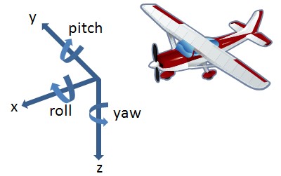
Visual interpretation of the Gyroscope measurement data
The LSM9DS0 is one such device. It can be obtained from Sparkfun.com (https://www.sparkfun.com/products/12636) for around $30. It supports both SPI or I2C transfer protocol. There are two separate slaves, one for the accelerometer and magnetometer data, and another for the gyroscope data. There are 6 registers for each output data set, There are multiple modes of operation that affect how the user can receive data. In Bypass mode, Output data can be addressed directly. In FIFO mode, data is sent to an FIFO register for quicker data retrieval and lower power consumption. In addition, interrupts can be configured so that polling for new data becomes unnecessary.
Before data can be presented in readable values, the full-scale values need to be set. The full set of configurable full-scale vaules can be found on page 13 of the datasheet (linked below), and can be modified through the registers CTRL_REG4_G (for gyroscope), CTRL_REG2_XM (for accelerometer), and CTRL_REG6_XM (for magnetometer). In the library, this can be done by making a call to 'setAccelScale(accel_scale aScl)', 'setGyroScale(gyro_scale gScl)', and 'setMagScale(mag_scale mScl)', where the parameters are declared as enumerated types. By default, the ranges are as follows:
- Magnetometer: +-2 gauss
- Accelerometer: +-2 g
- Gyroscope: +-245 dps
When the full-scale values are known, simply divide by 32,768 and then multiply by the full-scale value specified

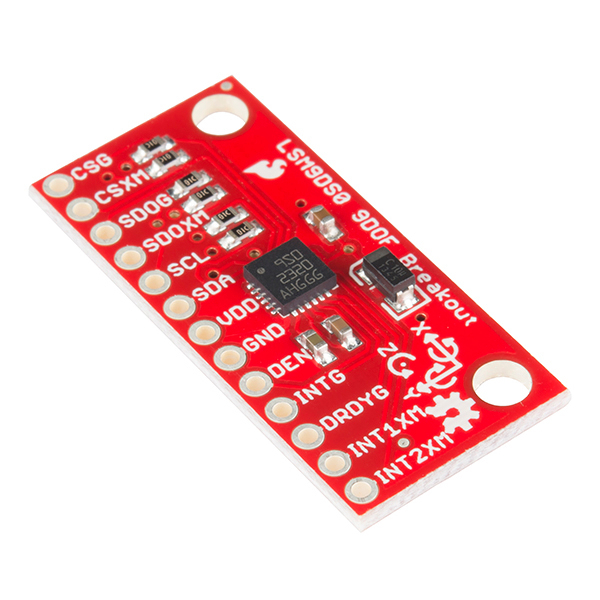
LSM9DS0 IMU device
Link to the LSM9DS0 schematic: https://cdn.sparkfun.com/assets/8/c/c/4/9/lsm9ds0_breakout-v10-schematic-.pdf The data sheet can be found here: https://cdn.sparkfun.com/assets/f/6/1/f/0/LSM9DS0.pdf
Demo
Below are examples of how to read output data from the device using an I2C bus. The configurations are left in their default state (Bypass mode, interrupts disabled, etc.), so minimal setup is required.
The data ready signal (DRDY_G) is used to signal when new data is available. This demo waits until the signal goes high before reading from the device to make sure that no old data is being read. When data is available, it is read from the device, and each dimension of each data set is stored in its own member variable. Before being printed to the screen, the raw data values, which range from 0 to 65536, are adjusted according to the full-scale ranges, which are left at default values.
The pin configurations are as follows:
- CSG | Vout
- CS_XM | Vout
- SDO_G | Gnd
- SDO_XM | Gnd
- SCL | p27
- SDA | p28
- Vdd | Vout
- GND | Gnd
- DEN | <Not connected>
- INT_G | <Not connected>
- DRDY_G | p23
- INT1_XM | <Not connected>
- INT2_XM | <Not connected>
Import libraryLSM9DS0
Allows for reading accelerometer, gyroscope, and magnetometer data from an LSM9DS0 IMU device
Demo:
main.cpp
#include "LSM9DS0.h"
#include "mbed.h"

// SDO_XM and SDO_G are both grounded, so our addresses are:
#define LSM9DS0_XM  0x1E // Would be 0x1E if SDO_XM is LOW
#define LSM9DS0_G   0x6A // Would be 0x6A if SDO_G is LOW

// Create an instance of the LSM9DS0 library called `dof` the
// parameters for this constructor are:
// pins,[gyro I2C address],[xm I2C add.]
LSM9DS0 dof(p28, p27, LSM9DS0_G, LSM9DS0_XM);
DigitalIn DReady(p23);

Serial pc(USBTX, USBRX); // tx, rx

bool printMag = true;
bool printAccel = true;
bool printGyro = true;

void setup()
{
    pc.baud(115200); // Start serial at 115200 bps
    // Use the begin() function to initialize the LSM9DS0 library.
    // You can either call it with no parameters (the easy way):
    uint16_t status = dof.begin();

    // Or call it with declarations for sensor scales and data rates:
    //uint16_t status = dof.begin(dof.G_SCALE_2000DPS,
    //                            dof.A_SCALE_6G, dof.M_SCALE_2GS);

    // begin() returns a 16-bit value which includes both the gyro
    // and accelerometers WHO_AM_I response. You can check this to
    // make sure communication was successful.
    pc.printf("LSM9DS0 WHO_AM_I's returned: 0x");
    pc.printf("%x\n",status);
    pc.printf("Should be 0x49D4\n");
    pc.printf("\n");
}

void printGyro() {
    dof.readGyro();

    pc.printf("G: ");

    pc.printf("%2f",dof.calcGyro(dof.gx));
    pc.printf(", ");
    pc.printf("%2f",dof.calcGyro(dof.gy));
    pc.printf(", ");
    pc.printf("%2f\n",dof.calcGyro(dof.gz));
}

void printAccel() {
    dof.readAccel();

    pc.printf("A: ");

    pc.printf("%2f",dof.calcAccel(dof.ax));
    pc.printf(", ");
    pc.printf("%2f",dof.calcAccel(dof.ay));
    pc.printf(", ");
    pc.printf("%2f\n",dof.calcAccel(dof.az));

}

void printMag() {
    dof.readMag();

    pc.printf("M: ");

    pc.printf("%2f",dof.calcMag(dof.mx));
    pc.printf(", ");
    pc.printf("%2f",dof.calcMag(dof.my));
    pc.printf(", ");
    pc.printf("%2f\n",dof.calcMag(dof.mz));
}

// Here's a fun function to calculate your heading, using Earth's
// magnetic field.
// It only works if the sensor is flat (z-axis normal to Earth).
// Additionally, you may need to add or subtract a declination
// angle to get the heading normalized to your location.
// See: http://www.ngdc.noaa.gov/geomag/declination.shtml
void printHeading(float hx, float hy)
{
    float heading;

    if (hy > 0) heading = 90 - (atan(hx / hy) * (180 / 3.14));
    else if (hy < 0) heading = - (atan(hx / hy) * (180 / 3.14));
    else // hy = 0
    {
        if (hx < 0) heading = 180;
        else heading = 0;
    }

    pc.printf("Heading: ");
    pc.printf("%2f\n",heading);
}

// Another fun function that does calculations based on the
// acclerometer data. This function will print your LSM9DS0's
// orientation -- it's roll and pitch angles.
void printOrientation(float x, float y, float z)
{
    float pitch, roll;

    pitch = atan2(x, sqrt(y * y) + (z * z));
    roll = atan2(y, sqrt(x * x) + (z * z));
    pitch *= 180.0 / 3.14;
    roll *= 180.0 / 3.14;

    pc.printf("Pitch, Roll: ");
    pc.printf("%2f",pitch);
    pc.printf(", ");
    pc.printf("%2f\n",roll);
}

void readData() {
    // To read from the device, you must first call the
    // readMag(), readAccel(), and readGyro() functions.
    // When this exits, it'll update the appropriate
    // variables ([mx, my, mz], [ax, ay, az], [gx, gy, gz])
    // with the most current data.

    dof.readMag();
    dof.readAccel();
    dof.readGyro();
}

void loop() {
    // Loop until the Data Ready signal goes high
    while (!Dready) {}

    readData();

    if (printGyro) printGyro();  // Print "G: gx, gy, gz"
    if (printAccel) printAccel(); // Print "A: ax, ay, az"
    if (printMag) printMag();   // Print "M: mx, my, mz"

    // Print the heading and orientation for fun!
    printHeading((float) dof.mx, (float) dof.my);
    printOrientation(dof.calcAccel(dof.ax), dof.calcAccel(dof.ay),
                     dof.calcAccel(dof.az));
    pc.printf("\n");

    wait(2);
}


int main()
{
    setup();
    while (true)
    {
      loop();
    }
}
Please log in to post comments.
