GD32-F450ZI
GD32-F450ZI-mbed development board with GD32F450ZI Chip
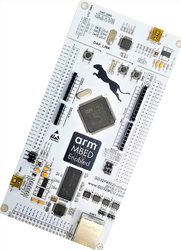
GD32F450ZI-mbed development board with GD32450ZI MCU on it, which can support Arduino. The GD32450ZI MCU is a 32-bits general-purpose microcontroller which based on the ARM® Cortex™-M4 processor with FPU.
Overview
The GD32F450ZI-mbed had been designed by GigaDevice. The board used GD32F450ZIT6 microcontroller which belongs to the high performance line of GD32 MCU Family. It is a 32-bits general-purpose microcontroller based on the ARM® Cortex®-M4 RISC core with best cost-performance ratio in terms of enhanced processing capacity, reduced power consumption and peripheral sets.
In order to fully use of the ARM® Cortex®-M4 core, GD32F450ZIT6 can operate at 200 MHz clock frequency as well as Flash accesses zero wait states to obtain a maximum DMIPS. GD32F450ZIT6 can provide up to 2048 KB on-chip Flash memory, 512 KB SRAM memory, lots of peripherals and interfaces. An extensive range of enhanced I/Os and peripherals were connected to MCU’s two APB buses. The GD32F450ZI-mbed also include Arduino interface which compatible with Arduino device.
Microcontroller features
- GD32F450ZIT6 in LQFP144 package
- Performance
- ARM® Cortex™-M4 CPU with FPU and MPU
- 200 MHz max CPU frequency
- Memory and memory expansion
- 2048 Kbytes of Flash memory
- 512 Kbytes of SRAM
- DMA
- SDIO
- EXMC
- TLI
- Clock management
- 4 to 32 MHz High Speed crystal oscillator (HXTAL)
- Internal 16 MHz RC oscillator (IRC16M)
- Internal 48 MHz RC oscillator (IRC48M)
- 32,768 Hz Low Speed crystal oscillator (LXTAL)
- Internal 32KHz RC oscillator (IRC32K)
- PLL clock source can be HXTAL, IRC16M
- HXTAL clock monitor
- Clock trim controller
- Reset and supply management
- Three power domains: VBAK, VDD/VDDA and 1.2V power domains
- Three power saving modes: Sleep, Deep-sleep and Standby modes
- 4K bytes backup SRAM powered by 1.2V can protection user application data when VDD shut down
- VDD , VDDA voltage range: 2.6V to 3.6V
- VBAk supply for RTC and backup registers
- Communication modules
- 114 general purpose I/O pins
- 4x USART modules + 4x UART modules
- 3x I2C modules
- 6x SPI modules
- 2x CAN 2.0B modules
- 2x I2S modules
- USB 2.0 FS
- Ethernet
- IPA
- Timers
- 2x 16-bit basic timers
- 2x 16-bit advanced timers
- 8x 16-bit general purpose timers
- 2x 32-bit general purpose timers
- 2x watchdog timers
- Analog Modules
- 3x 12-bit ADCs with 16 channels
- 2x 12-bit DAC channels
- Security and integrity modules
- Hardware CRC calculation unit
- Embedded flash security
GD32F450ZI-mbed board features
Following figure indicates the GD32F450ZI-mbed board’s signal connections with the main components and extension connectors.

Main Feature Of The Board:
- Three User LEDs(LED1, LED2 and LED3)
- Three push buttons(K1, K2 and reset)
- Four modules(I2C, CAN0, CAN1 and SPI) on-board
- Ethernet 10/100 controller with on-board transceiver and RJ45 connector
- USB 2.0 FS with Micro connector
- SDRAM(MT48LZ16M16A2P)
- LCD interface(RGB)
- DAP_Link
- Arduino interface
- Power-supply options: USB 2.0 FS, DAP_Link USB and Arduino headers
Board Pinout
Following figure indicates the GD32F450ZI-mbed board’s Pinouts.


Arduino Headers Pinout

Technical references
Please download
- GD32F450ZIT6’s chip datasheet: http://gd32mcu.21ic.com/data/documents/shujushouce/GD32F450xx_Datasheet_Rev1.1.pdf
- Chip's User manual: http://gd32mcu.21ic.com/data/documents/yingyongbiji/GD32F4xx_User_Manual_EN_V1.2.pdf
- GD32F450ZI-mbed board’s schematic: http://gd32mcu.21ic.com/data/documents/kaifaban/GD32F450ZI-MBED-V1.1.pdf
- DAPLink bin file:/media/uploads/c_jin/daplink_450zi_if.bin
Getting started with GD32F450ZI-mbed
1. Configure the development environment according to the method provided on the ARM web page.
2. Connect the board and PC with USB cable. Open DOS window, change directory to locally working directory.
3. Import a program from MBED. Change directory to mbed-os-example-blinky and compile the program.


4. The image is in “.\BUILD\GD32_F450ZI\ARM\mbed-os-example-blinky.bin”. Save the program binary file to your mbed Microcontroller Disk(DAPLINK). When the Reset Button is pressed, the LED1 will blink.

5. To debug using a desktop IDE such as Keil uVision, use the “mbed export” command to generate project files.

Open the project in Keil uVision, select GD32F450ZI as Device. By selecting GD32F450ZI as Device, we can compile and debug the mbed program after downloading it into the board.


To compile a program for this board using Mbed CLI, use GD32_F450ZI as the target name.
Board Partner

GigaDevice
GigaDevice, founded in Silicon Valley in 2005, is a leading fabless company engaged in advanced memory technology and IC solutions. The company has successfully completed the IPO at Shanghai Stock Exchange in 2016. GigaDevice provides a wide range of high performance Flash memory and 32-bit general-purpose MCU products. GigaDevice is among the companies that pioneered SPI NOR Flash memory and is currently ranked number three in the world in this market segment with more than 1 billion units shipped every year.
 Mbed Enabled
- Advanced
- Baseline
Mbed OS support
- Mbed OS 5.11
- Mbed OS 5.12
- Mbed OS 5.13
- Mbed OS 5.14
- Mbed OS 5.15
- Mbed OS 6.0
- Mbed OS 6.1
- Mbed OS 6.10
- Mbed OS 6.11
- Mbed OS 6.12
- Mbed OS 6.13
- Mbed OS 6.14
- Mbed OS 6.15
- Mbed OS 6.2
- Mbed OS 6.3
- Mbed OS 6.4
- Mbed OS 6.5
- Mbed OS 6.6
- Mbed OS 6.7
- Mbed OS 6.8
- Mbed OS 6.9
Example programs