MCP3221
Note
This page has been moved to the Components section of the website. Please see http://developer.mbed.org/components/MCP3221-ADC/ .
Introduction
This library was written because I needed to an analogIn accurately in the range 2.5v to 5.0v, at a resolution of 20mV.
I was using a comparator circuit designed around an opAmp to level shift the signal, but realised there were better ways of doing it with an ADC being supplied from 5.0v.
If you use an external ADC then these give a reading referenced to the supply voltage. So, if you use an ADC such as an MCP3221, and supply it with 5.0v, then the ain can swing between 0 and 5.0v.
The chosen IC is an I2C device, and at 12BIT, it has a resolution of 4096 "steps" between Vss (usually GND) and Vdd (Supply voltage).
This means that if it is supplied with 5.0v, it has a resolution of approx 1mV.
Notes on Addressing
This library is for the default part : MCP3221A5T-I/OT
The "A5" in the part number denotes the specific address of this part. This ADC is available with different addresses (different part codes) so that you can have more than 1 on the I2C bus.
Studying the datasheet showed that it is not a completely standard I2C part. You cannot write to an MCP3221, it has no writable registers. You open a conversation with it by sending it a byte terminating in a "1" bit, these bytes are usually "reads" in the I2C architecture.
MCP3221 also requires an ACKnowledge between each byte it sends, before it will send the next byte. So we need to be a bit manual with how we talk to it.
It also needs an (NOT) ACKnowledge after the second byte or it will keep sending bytes (continuous sampling)(You can continuous sample from it if you want, but this library does not support that) This is a simple, "set it up and read from it, getting a value back as a voltage" library.
to communicate with it you must..
- I2C.START
- Send 8 bit device/ part address to open conversation. (See .h file for part explanation)
- read a byte (with ACK)
- read a byte (with NAK)
- I2C.STOP
- Convert the 2 byte value to something meaningful by referencing the supply voltage
SPECIAL NOTE
There seems to be a typo copied across multiple datasheets. The part code is 1001, so the initial "open conversation byte" is 10011011, not as described in the text of the datasheet. The pictures on the datasheets have it correct.
Library
Import libraryMCP3221
A library for the MCP3221 12BIT I2C ADC. (2.7 - 5.0v)
Example Program
Import programMCP3221_TEST
MCP3221_Test Program.
Note: Instantiate with, SDA, SCL, and the supply voltage it is running on. then "read()" returns a float of the voltage on the ain pin. No further processing of the return value is required.
#include "mbed.h"
#include "MCP3221.h"

DigitalOut myled(LED1);

Serial pc(USBTX, USBRX); // tx, rx
AnalogIn ain(p20);
MCP3221 adc(p9, p10, 5.0); //sda, scl, supplyVoltage

int main() {

    wait(1);
    while (1) {

        pc.printf("ain: %f :: ", ain.read()*3.3);
        pc.printf("adc: %f \r\n", adc.read());

        myled=!myled;

        wait(1);
    }
}
Physical
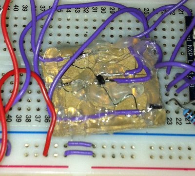
Haven't got a breakout board for a SOT23 package ? (3mm x 2mm).

You can solder onto the two pins on one side quite easily, they are 2mm apart after all. The three on the same side are a little more challenging. I did this without a scope, in about 10 mins with a normal fine point. (nothing fancy).
- Tin each leg very quickly with a fine iron.
- Tin the ends of some 2 inch strands of rework wire.
- Hold each piece of rework wire onto a leg and dab with your iron.
- Put a big dollop of hotmelt glue on a small piece of cardboard and put the package on the top. Pressing gently to secure.
- Tin the other end of each piece of rework wire, wrap around a tinned end of a breadboard wire, and then apply heat to solder together. (a bit more solder doesn't hurt)
- secure everything with more hotmelt glue before using. Those tiny legs are easily pulled off if you don't.

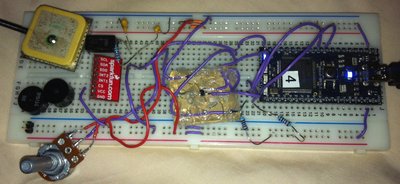
Note to self: must buy some more breadboards, and be tidier if other people will see it
I shall quickly describe this.
MCP3221 is connected to p9 and p10, SDA, SCL. VU is connected to the side rail to give it 5.0v The SDA amd SCL are pulled up with 10K resistors from this rail. I have put a pot across GND - 5V with the sweeper going to AIN on the ADC. The sweeper also goes to p20 on the mbed.
There's a 10uF and a 0.1uF Cap from the 5v rail to GND to stop transients, but this probably isn't needed on this particular design, it's on the reference design on the datasheet. I've added a 10K resistor to stop the 10uF getting hot. (it probably should be lower, but I had a packet of 10K resistors to hand, as they are the recommended pullups for this part)
Speed
The pullups govern the speed it can run at.
- Use 10k for 100kHz
- Use 2k for 400kHz
